Mist outlet air duct device of ultrasonic humidifier

A humidifier and ultrasonic technology, applied in ultrasonic humidifiers, air humidification systems, heating methods, etc., can solve the problems of uneven water mist particles, volume water in humidifiers, and inability to guarantee the quality of air humidification, so as to improve efficiency and improve efficiency. Humidification quality, simple and practical structure, clever design effect

Inactive Publication Date: 2011-02-09
MIDEA GRP CO LTD
View PDF6 Cites 20 Cited by
  • Summary
  • Abstract
  • Description
  • Claims
  • Application Information

AI Technical Summary

Problems solved by technology

[0002] The water mist of the traditional ultrasonic humidifier is excited by the vibrating plate and then discharged directly through the mist outlet. Due to the unevenness of t...

Method used


Image

  • Mist outlet air duct device of ultrasonic humidifier
  • Mist outlet air duct device of ultrasonic humidifier
  • Mist outlet air duct device of ultrasonic humidifier

Examples


Embodiment Construction

[0013] The specific implementation manners of the present invention will be further described below in conjunction with the drawings and examples.

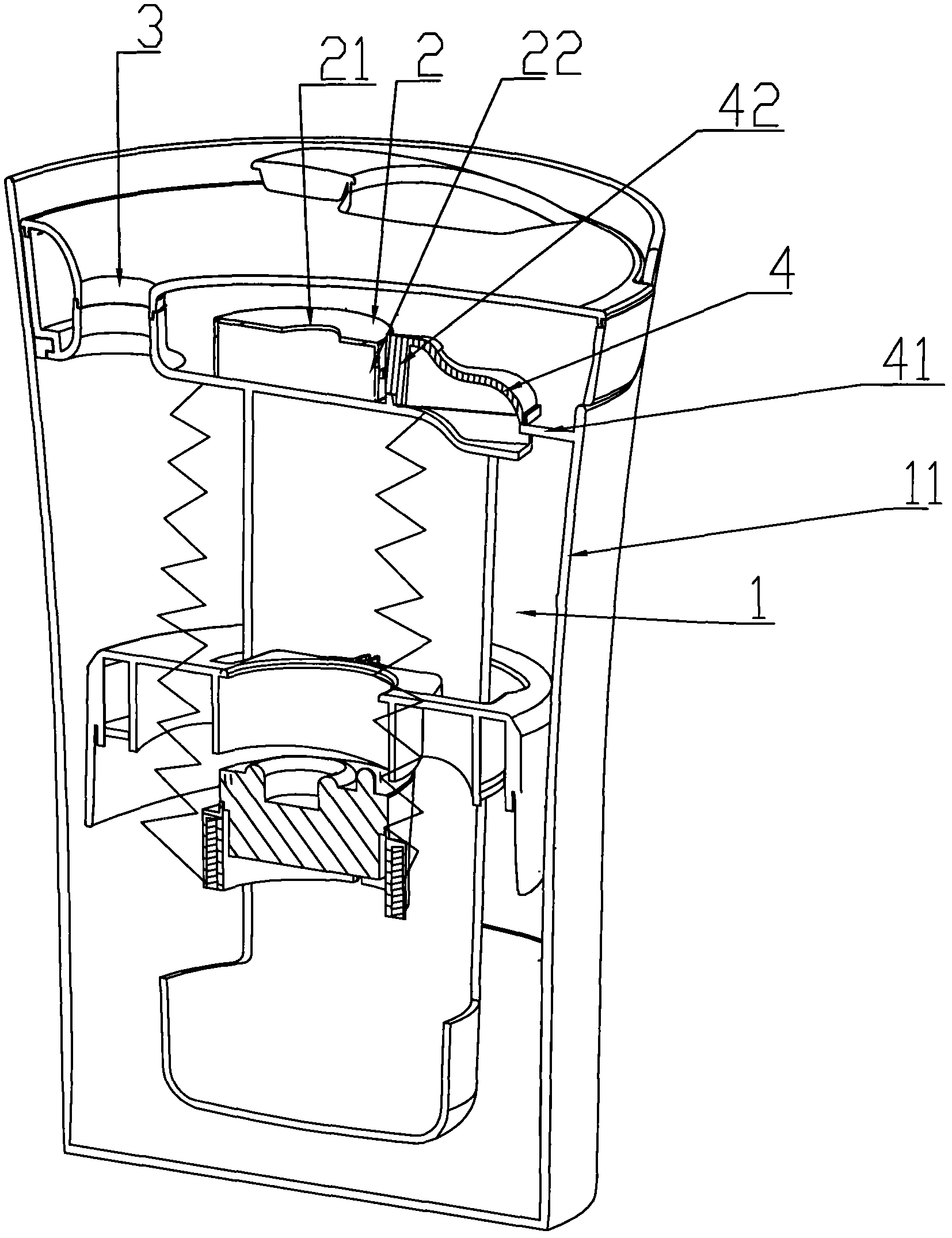
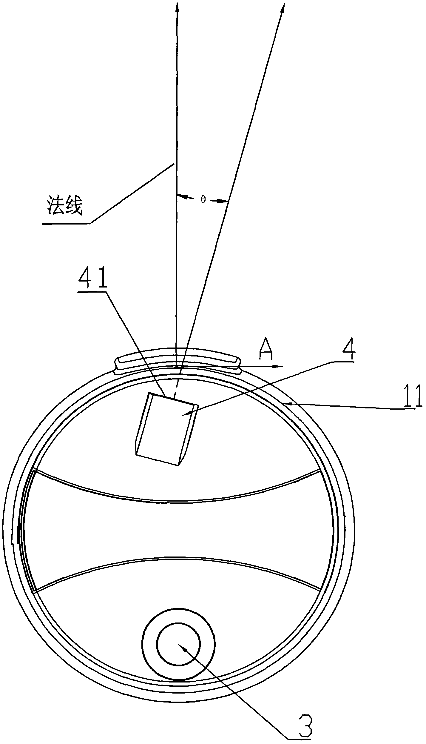
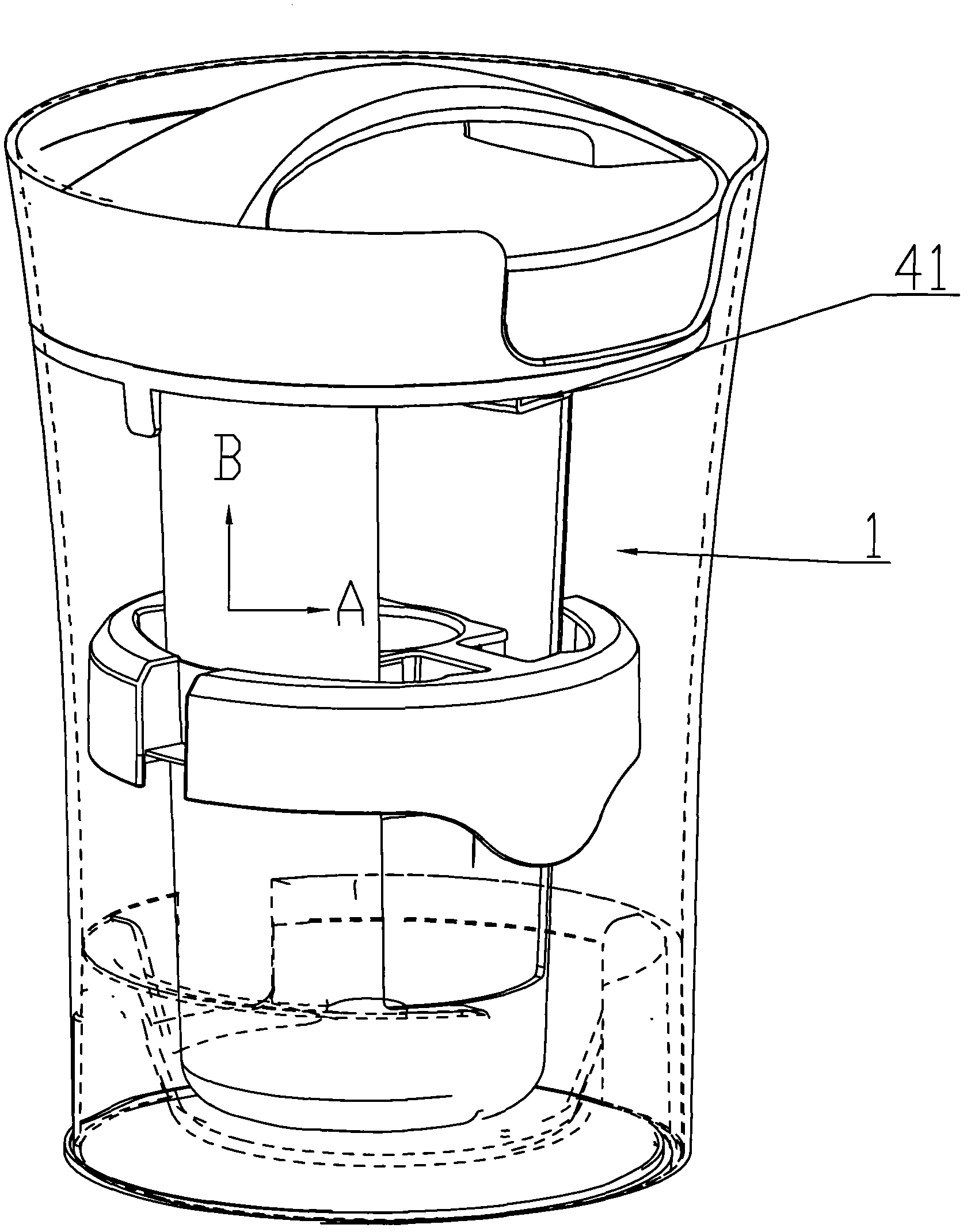
[0014] Such as figure 1 , figure 2 , image 3 As shown, the present invention includes an atomization area 1, a fan 2, an air duct 4 and a mist outlet 3; the atomization area 1 is a rotating body structure, the mist outlet 3 is placed on the top of the atomization area 1, and the air duct 4 contains an air outlet 41 and air inlet 42; fan 2 contains fan air inlet 21 and fan outlet 22, fan outlet 22 is connected to air inlet 42 of air duct 4; air outlet 41 of air duct 4 is located in atomization area 1 and placed in atomization area 1 At the top, the direction of the air outlet 41 forms an angle θ with the normal direction of the inner wall 11 of the atomization zone 1, and 0 figure 2 As shown, the water mist or air in the atomization area 1 is driven to make a circular motion; at the same time, the blown wind makes the atomizati...


PUM


Abstract

The invention aims at providing a mist outlet air duct device of an ultrasonic humidifier, comprising a fan, an air duct, an atomization area and a mist outlet, wherein the air duct is provided with an air outlet positioned in the atomization area. The mist outlet air duct device is characterized in that the direction of the air outlet and the normal direction of the inner wall of the atomization area form an angle theta which is more than 0 degree and less than 90 degrees. In the mist outlet air duct device, air is exhausted from the air outlet and is blown onto the inner wall of the atomization area so as to form movement tangential to the inner wall of the atomization area and drive the mist to do spiral movement. Simultaneously, the air pressure provided by the fan forces the mist to spiral upward from the bottom part till the excited mist is exhausted from the mist outlet. The mist has a long spiral process in the exhaust process, and is contacted with the inner wall of the atomization area for long time; large-particle water mists can be agglutinated again and fall into water or are coagulated at the inner wall of the atomization area, and all the small-particle water mists are exhausted in the environment. Therefore, the mist outlet air duct device can avoid the problem that the traditional humidifier is easy to lead the surrounding objects to collect water, and can improve the efficiency and quality for humidifying the air, thus achieving the purpose of high-efficiency humidification.

Description

technical field [0001] The invention relates to an ultrasonic air humidifier, in particular to an ultrasonic humidifier fog outlet air channel device. Background technique [0002] The water mist of the traditional ultrasonic humidifier is excited by the vibrating plate and then discharged directly through the mist outlet. Due to the uneven particles of the discharged water mist, the quality of air humidification cannot be guaranteed, and at the same time, it is easy to make the objects around the humidifier accumulate water. To solve this problem, it is necessary to ensure that the water mist discharged from the humidifier is fine and uniform. Contents of the invention [0003] The purpose of the present invention is to overcome the disadvantages of the prior art, to provide an ultrasonic humidifier with a simple and practical structure, which can avoid the problem that the existing humidifiers tend to make the surrounding objects accumulate water, and can improve the air...

Claims


Application Information

Patent Timeline
IPC IPC(8): F24F6/12
CPCY02B30/80Y02B30/70
Inventor 李凯王辉朴喜千罗毅董燕燕黄平飞
Owner MIDEA GRP CO LTD
Why Eureka
Try Eureka