Sauna apparatus

a technology of air conditioner and air filter, which is applied in the direction of machine/engine, combustible gas purification/modification, separation process, etc., can solve the problems of increasing air flow resistance, reducing the efficiency of humidification of air, and increasing the humidity of air in the bathroom. , to achieve the effect of increasing humidity, simple structure and increasing humidity

Active Publication Date: 2011-12-06
PANASONIC CORP
View PDF17 Cites 5 Cited by
  • Summary
  • Abstract
  • Description
  • Claims
  • Application Information

AI Technical Summary

Benefits of technology

[0008]The present invention provides a sauna apparatus, which produces relatively tiny water droplets and increases humidity in a bathroom even with a method of spraying the droplets in a blow channel for increasing humidity. Having a relatively simple structure, it prevents large diameter droplets from being blown into the bathroom.
[0009]The sauna apparatus of the present invention includes an air blower, a blow channel, and a humidifier. The air blower suctions and blows air. The blow channel conveys the suctioned air and humidified air. The humidifier has a sprayer for spraying water for humidification into the air passing through the blow channel so as to humidify the air, and a spray-water droplet splitter. The spray-water droplet splitter is installed facing toward the sprayer that sprays the water for humidification. By letting the sprayed water droplets collide with the splitter, the water droplets are split into much finer water droplets. Since the spray-water droplet splitter splits fine water droplets sprayed by the sprayer into much finer droplets, the sauna apparatus of this invention increases efficiency of humidification, and does not blow out large diameter droplets.

Problems solved by technology

Accordingly, the suctioned air is not efficiently humidified and an effective humidification amount is not obtained.
However, such constitution increases air flow resistance, or makes the constitution complicated.

Method used


Image

  • Sauna apparatus
  • Sauna apparatus
  • Sauna apparatus

Examples


Embodiment Construction

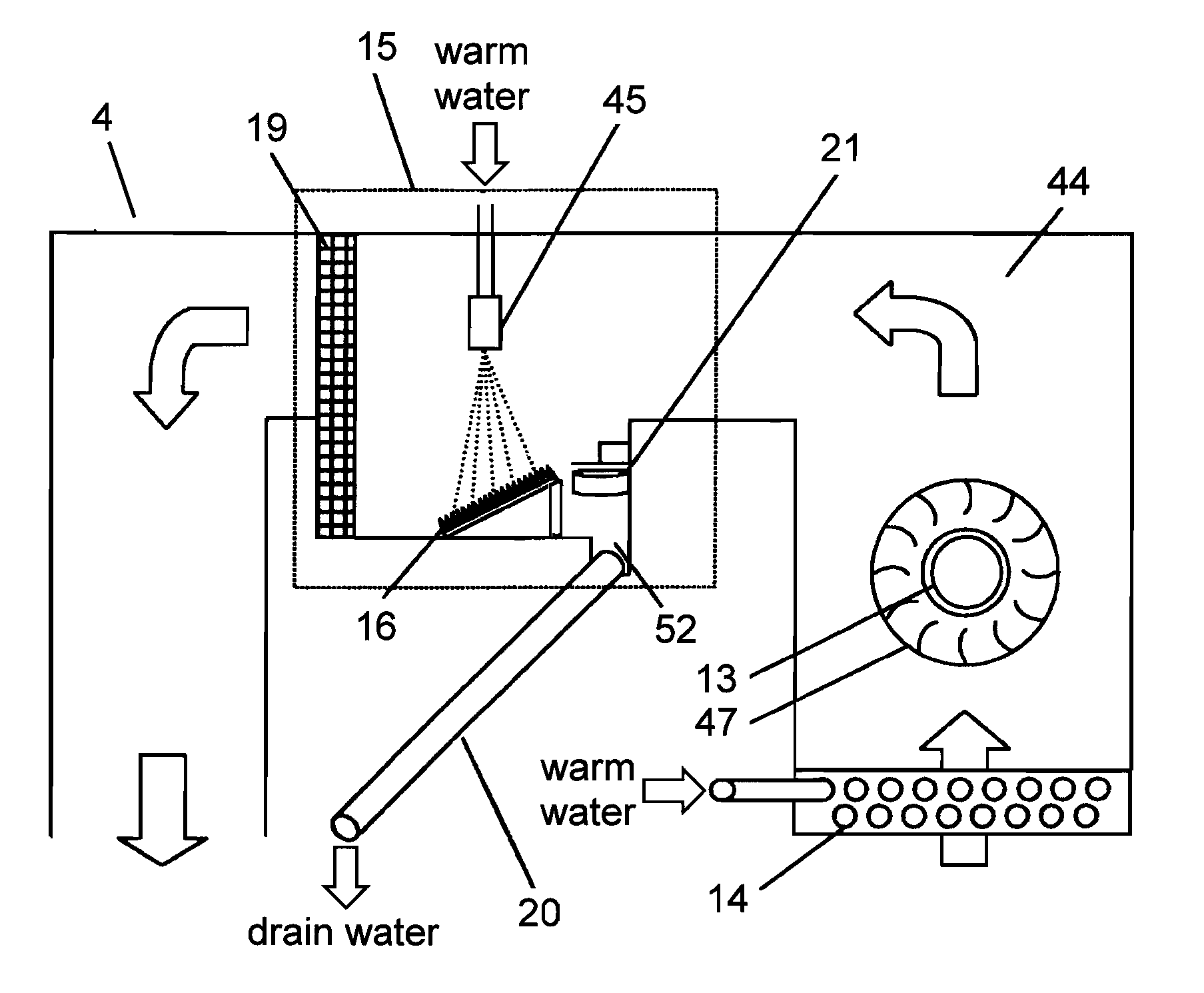
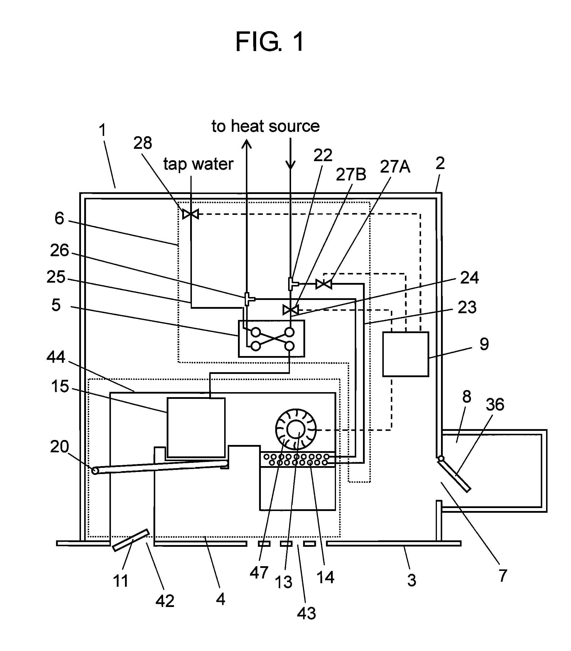
[0020]FIG. 1 is a block diagram schematically showing a sauna apparatus according to an embodiment of the present invention. Sauna apparatus 1 includes exterior package 2, front panel 3, sauna module 4, heat supplier 6, ventilation unit 8, and controller 9. Exterior package 2 constitutes an outer shell of sauna apparatus 1. Front panel 3 constitutes a wall of exterior package 2 adjacent to a bathroom. Sauna module 4 suctions air from the bathroom, heats and humidifies the air and then blows it out again to the bathroom. Heat supplier 6 includes plate heat exchanger 5. Ventilation unit 8 is installed at a side of exterior package 2 and is attached to opening 7 communicated to a blow channel. Controller 9 controls these constituent members. Hereinafter, each constitution is specifically described.

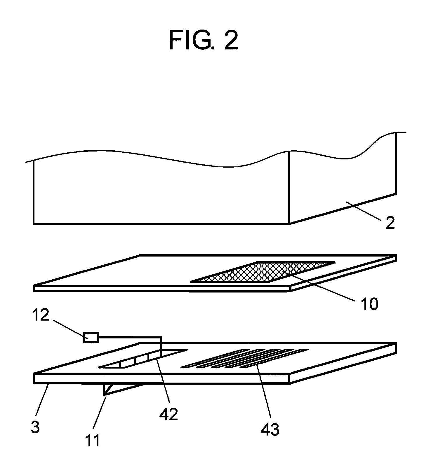
[0021]FIG. 2 is a schematic exploded view of the apparatus in a state in which front panel 3 is detached. Front panel 3 is provided with suction port 43 for suctioning air from the bathroom a...


PUM

PropertyMeasurementUnit
thickaaaaaaaaaa
heightaaaaaaaaaa
radiusaaaaaaaaaa

Abstract

A sauna apparatus includes an air blower, a blow channel and a humidifier. The air blower suctions and blows air. The blow channel conveys the suctioned air and humidified air. The humidifier has a sprayer that sprays humidifying water into the air passing through the blow channel for humidification, and a spray-water droplet splitter installed in a direction to which the sprayer sprays the water for humidification. By letting the sprayed water droplets collide with the splitter, the water droplets are split into much finer water droplets.

Description

[0001]This application is a U.S. National phase application of PCT International Application PCT / JP2007 / 054766, filed Mar. 12, 2007.TECHNICAL FIELD[0002]This invention relates to a sauna apparatus for heating and humidifying a room such as a bathroom, to thereby convert the room into a sauna space.BACKGROUND ART[0003]FIG. 10 is a schematic diagram showing a constitution of a conventional sauna apparatus. This type of sauna apparatus is disclosed in Unexamined Japanese Patent Publication No. H2-264659, for instance. A conventional sauna apparatus is described hereinafter.[0004]The sauna apparatus has discharge port 102 and suction port 103 both opening into bathroom 101. Suction port 103 is communicated to discharge port 102 through blow channel 104. In blow channel 104, spray nozzle 105 (hereinafter, referred as ‘nozzle’) is installed. Nozzle 105 is connected to warm water supply 106. Cross flow fan 107 is installed at suction port 103.[0005]Hot air generator 108 installed in a midd...

Claims


Application Information

Patent Timeline
Patent Type & Authority Patents(United States)
IPC IPC(8): B01F3/04
CPCA61H33/063A61H33/065
Inventor SAITOU, KAZUHIRONISHIZURU, YOSHIHIRO
Owner PANASONIC CORP
Why Eureka
Try Eureka