LED driving loop

A technology of LED driving and driving circuit, applied in the direction of electric lamp circuit layout, lighting device, light source, etc., can solve the problem of brightness drop, it is difficult to adjust the brightness of lighting fixtures in a large scale, etc., so as to reduce the brightness difference and reduce the impact. Effect

Inactive Publication Date: 2013-10-30
赵熙
View PDF1 Cites 0 Cited by
  • Summary
  • Abstract
  • Description
  • Claims
  • Application Information

AI Technical Summary

Problems solved by technology

However, in this method, the difference in the voltage between the base and the emitter of each transistor used for driving and the emitter resistance will cause an error (such an error must exist), because the base of each transistor used is are connected to each other, so the base potential of the transistor is determined by the lowest potential among them. The lowest potential value is: the potential between the base and the emitter + the emitter resistance × the minimum value of the value calculated by the emitter current value →, so As a result, the drive current of each column of LEDs is different, and the luminance is also different. When a drive transistor breaks down or an LED column is disconnected, it will affect the drive current value of the entire LED, making the luminance of the entire LED and it is difficult to adjust the luminance of lighting fixtures in a large scale

Method used


Image

  • LED driving loop

Examples


Embodiment Construction

[0016] The preferred embodiments of the present invention will be further described below in conjunction with the accompanying drawings.

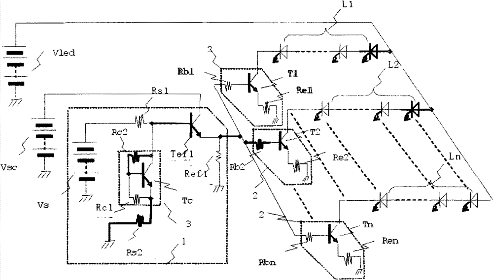
[0017] Accompanying drawing is the schematic diagram of LED drive circuit in the preferred embodiment of the present invention, and the function of this LED drive circuit is divided into one or several serial LED columns Ln (n: 1~n) (one end connects power supply Vled, the other end connects drive The drive unit 2) of each LED column Ln and the control unit 1 that controls the LED drive unit 2 and controls the current value.

[0018] The driving part 2 is made up of n transistors Tn (n: 1~n), and the collector of the transistor {is used to drive k (k is a natural number more than 1) in series, n columns (n ​​is a natural number more than 1) ) composed of k×n LEDs} are connected to the LED column Ln (n: 1~n), the emitter is connected to Ren (n: 1~n), and the base is connected to Rbn (n: 1~n).

[0019] The value of resistor Ren is set in con...


PUM


Abstract

The invention provides an LED driving loop. The driving loop can work under a low voltage and is not be affected by various interferences caused by installing place and the surrounding environment; the driving loop has small driving current and can stably work when the temperature is changed and can adjust the glaze. The driving loop for LED is characterized by comprising a driving part (for providing power and driving one or a plurality of LED arrays Ln formed by serially connecting one or more LEDs) and a control part, wherein the control part comprises a resistor Rs1 and Rs2 and a temperature correction mechanism part which includes a transistor Tc; the collector of the transistor and the base electrode are connected with an Rc2; the base electrode and the emitter are connected with an Rc1; through adjusting the ratio of the Rc1 and R2, the transistor Tc is combined with one part and the thermal combining degree is adjusted; the temperature of the driving loop is set to an expected property.

Description

technical field [0001] The invention relates to an LED driving circuit and an LED lighting device using the driving circuit. Background technique [0002] With the emergence of white-like LEDs and the improvement of luminous efficiency due to technological progress, lighting sources using LEDs can improve energy efficiency more than the light sources of incandescent lamps commonly used in the past. Now it is commercialized for small and thin LED lighting devices. A lot to try. However, LEDs are different from conventional light sources represented by incandescent lamps. Because they are semiconductors, in order to suppress the temperature rise during operation, the current passing through the LED must not only be sufficient, but also be stable when the temperature and voltage fluctuate. The current value should be set within the rated range. In order to feature the high efficiency of LED, the efficiency must be higher than that of conventional lighting. Therefore, while im...

Claims


Application Information

Patent Timeline
Patent Type & Authority Patents(China)
IPC IPC(8): H05B37/02
Inventor 椋田洋治小室熙美陈玲潘奎宇
Owner 赵熙
Why Eureka
Try Eureka