Display apparatus having uniformity function of pixel luminescence frequency and display method

Inactive Publication Date: 2007-04-17
PANASONIC CORP
View PDF18 Cites 4 Cited by
  • Summary
  • Abstract
  • Description
  • Claims
  • Application Information

AI Technical Summary

Benefits of technology

[0016]The present invention is for solving such tasks, and has the objective that a display apparatus and displaying met

Problems solved by technology

However, in the method in which a material aspect of the fluorescent material and the discharge gas used for the plasma display is improved, there is a problem that it requires a long study time and a great study expense.
Also, in the method in which the discharge number per unit time period, which participates in luminescence of the

Method used


Image

  • Display apparatus having uniformity function of pixel luminescence frequency and display method
  • Display apparatus having uniformity function of pixel luminescence frequency and display method
  • Display apparatus having uniformity function of pixel luminescence frequency and display method

Examples


first embodiment

[0044]the present invention will be explained using FIG. 1 and FIG. 2.

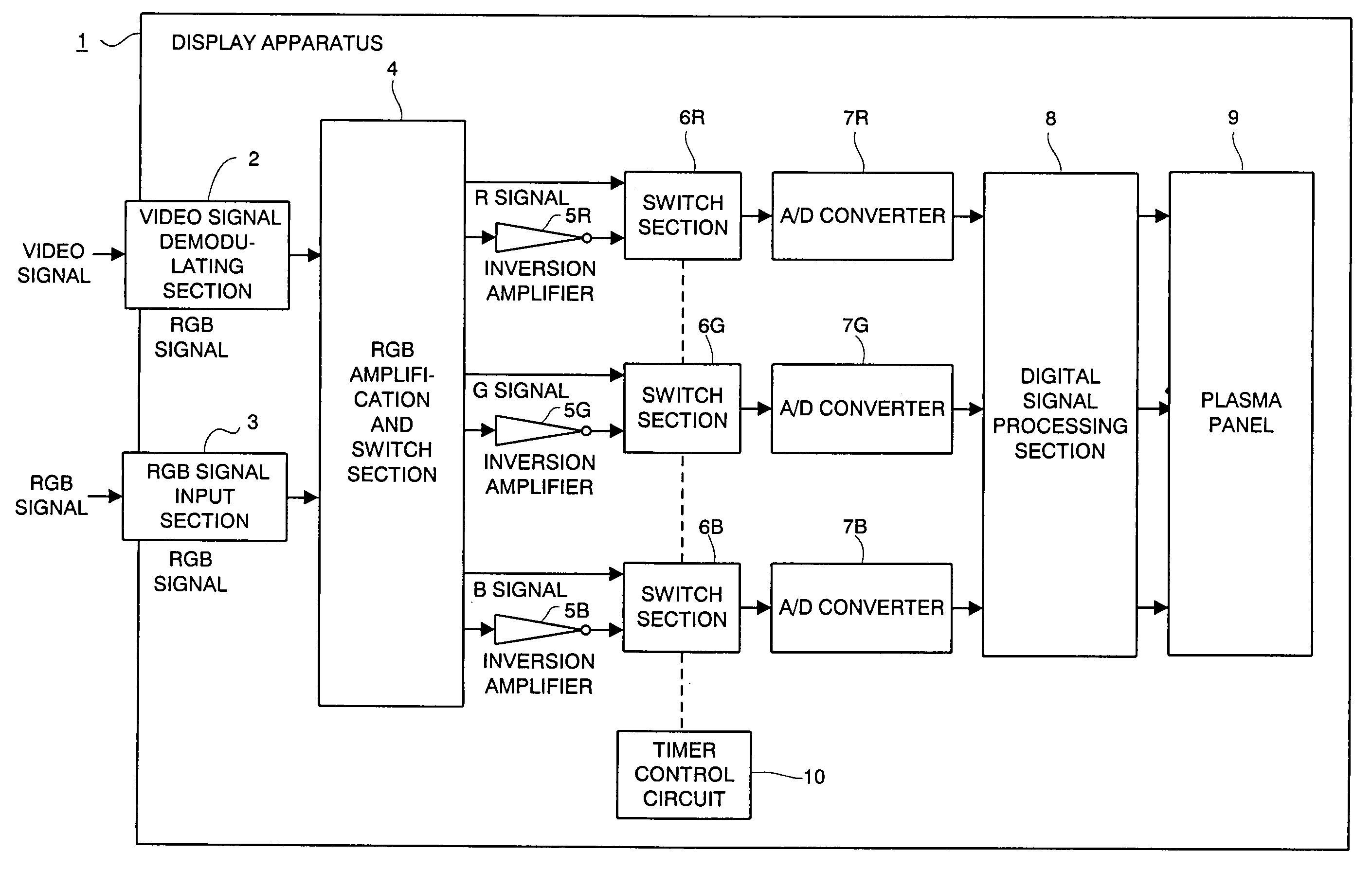
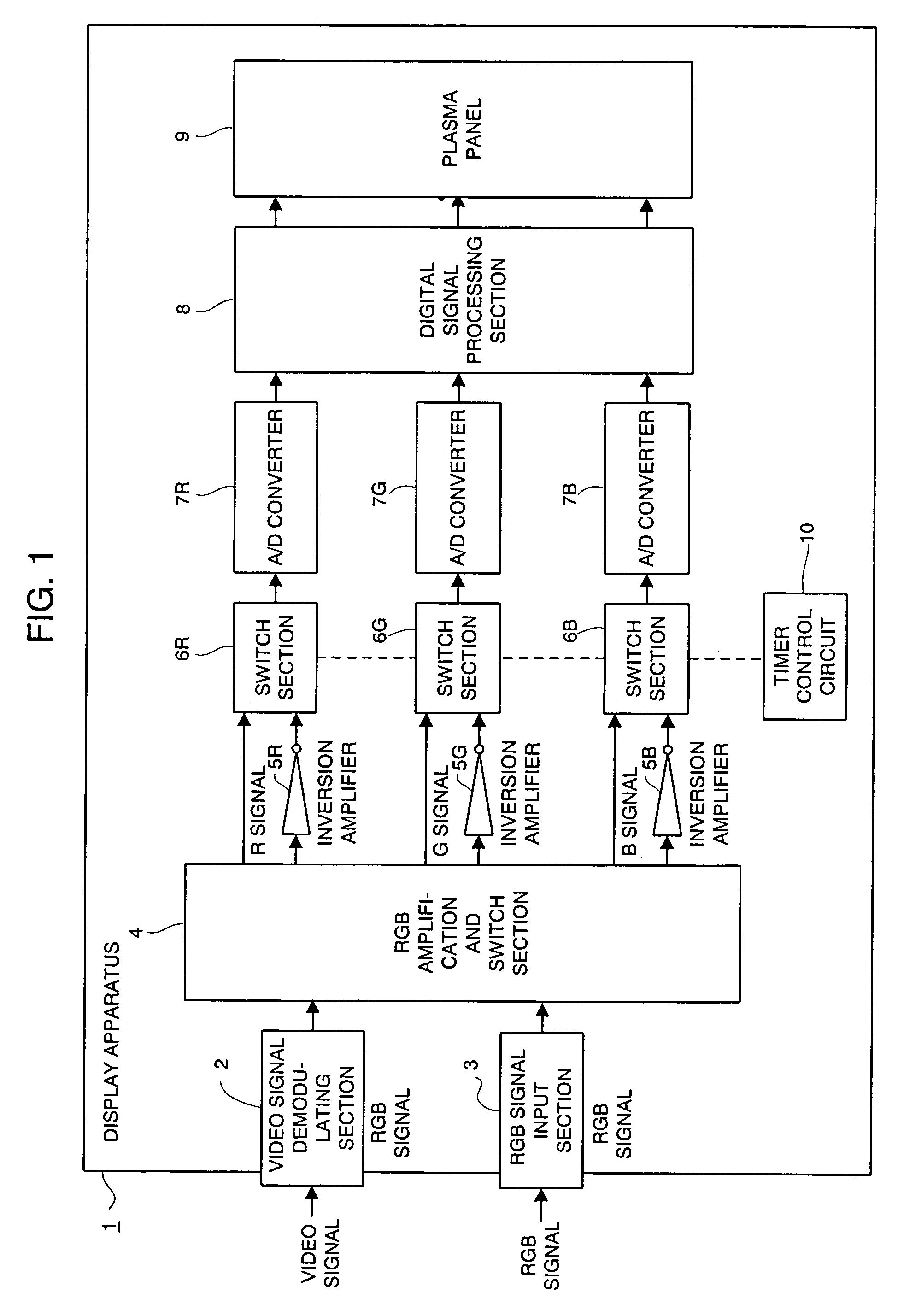
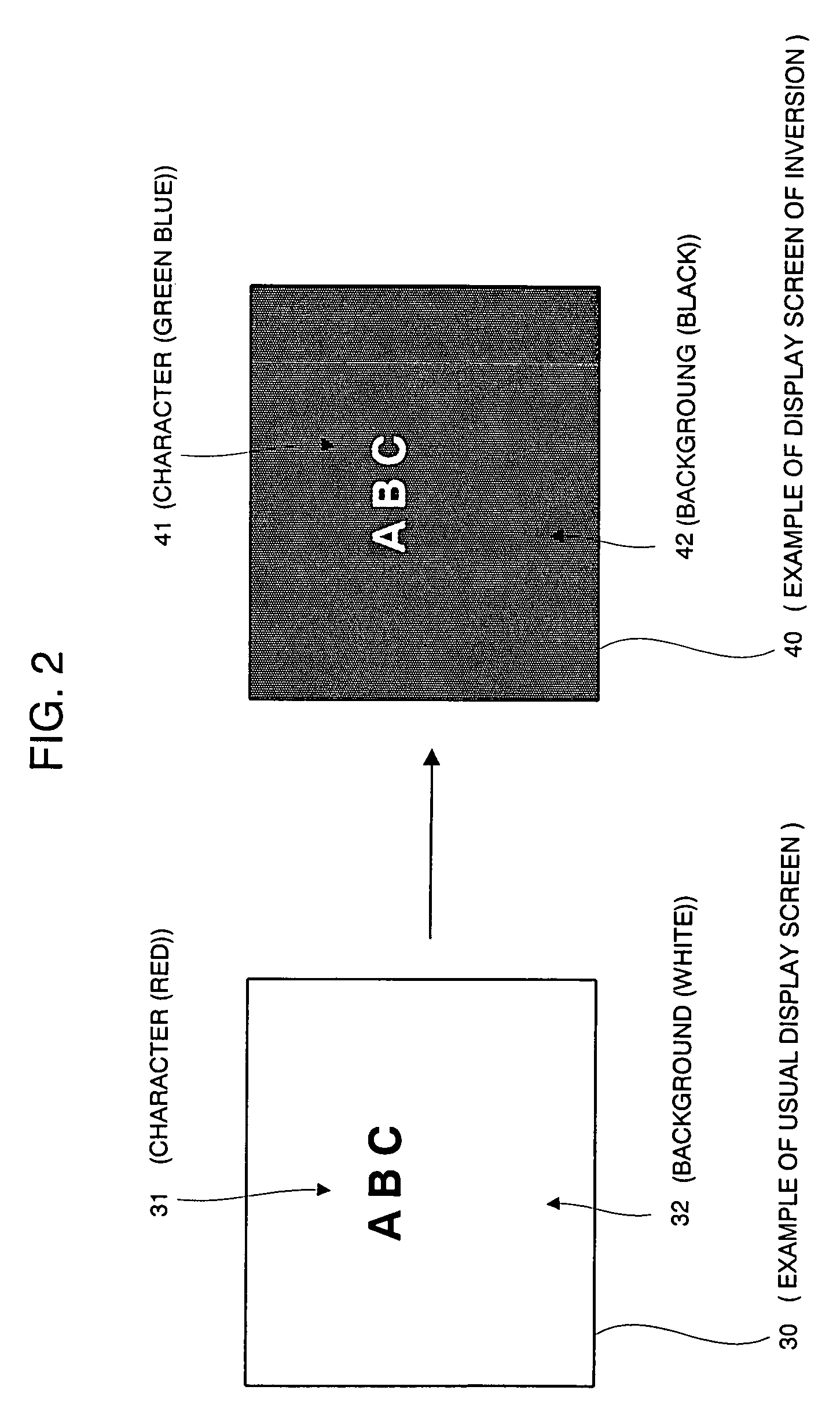
[0045]FIG. 1 is an arrangement view of the first embodiment in accordance with the present invention. FIG. 2 is an example of a screen on which a display apparatus in accordance with the present invention shows an image.

[0046]In FIG. 1, 1 is a display apparatus, which is for showing a video signal that is input from a device (a video deck, a personal computer and a television tuner, for example) for generating a video signal. The display apparatus 1 is constructed of a video signal demodulating section 2, to which a video signal is input, an RGB signal input section 3, to which an RGB signal is input, an RGB amplification and switch section 4, an inversion amplifier 5R, an inversion amplifier 5G, an inversion amplifier 5B, a switch section 6R, a switch section 6G, a switch section 6B, an A / D converter 7R, an A / D converter 7G, an A / D converter 7B, a digital signal processing section 8, a plasma panel 9, a timer con...


PUM


Abstract

Means for inverting levels of R, G and B signals that are analog signals, and are primary color signals of video signals, in response to an instruction signal for inverting luminance, and means for displaying the above-described inverted video signals are included.

Description

BACKGROUND OF THE INVENTION[0001]The present invention relates to a technology for reducing an aged variation of luminance of a display apparatus, and especially, to a technology capable of reducing luminance deterioration due to an aged variation of a pixel fluorescent material of a plasma display, which selectively emits light.[0002]A prior art will be explained using FIG. 4.[0003]FIG. 4 is a block diagram of a conventional display apparatus.[0004]In FIG. 4, 200 is a display apparatus, which is for displaying a video signal that is input from an outside. The display apparatus 200 is constructed of a video signal demodulating section 201, an RGB signal input section 202, an RGB amplification switch section 203, an A / D converter 204R, an A / D converter 204G, an A / D converter 204B, a digital signal processing section 205, and a plasma panel 206.[0005]Next, operation of the above-mentioned conventional display apparatus 200 will be explained.[0006]The video signal demodulating section ...

Claims


Application Information

Patent Timeline
IPC IPC(8): G09G3/28H04N5/66G09G3/20G09G3/22G09G3/296
CPCG09G3/22G09G3/28G09G2320/043G09G2320/06G09G3/2003G09G2320/0242
Inventor YASHIRO, JUNICHIIMAJOU, MAKOTO
Owner PANASONIC CORP
Why Eureka
Try Eureka