
Water-pump piloting automatic vacuum suction device

An automatic device and vacuum suction technology, which is applied in the direction of pumps, drive pumps, non-variable pumps, etc., can solve the problems of easily damaged impellers of water ring vacuum pumps, reduced water pump efficiency, and difficult maintenance of bottom felling.

Inactive Publication Date: 2012-05-02
张庆玉
View PDF0 Cites 0 Cited by
  • Summary
  • Abstract
  • Description
  • Claims
  • Application Information

AI Technical Summary

Problems solved by technology

[0002] The water pump is a general-purpose equipment with a large number of applications. Before the pump is running, the pump chamber must be filled with water. To fill the water, a bottom cutting should be installed at the bottom of the suction pipe of the pump. Often, the bottom cutting is not tightly sealed. The water pump cavity is not filled with diversion water, so that the water pump cannot start and run. The bottom felling is not only difficult to maintain, but also causes resistance, reduces the efficiency of the water pump, reduces the suction lift of the water pump, wastes energy, and affects the service life of the water pump.
[0003] The State Council listed the bottomless water pump as a national key energy-saving promotion project in 1978. At present, large-scale water pumps generally adopt the method of water ring vacuum pump to absorb and divert water to remove the bottom. Disadvantages such as damage to the impeller of the water ring vacuum pump and large maintenance

Method used


Image

  • Water-pump piloting automatic vacuum suction device
  • Water-pump piloting automatic vacuum suction device
  • Water-pump piloting automatic vacuum suction device

Examples


Embodiment Construction

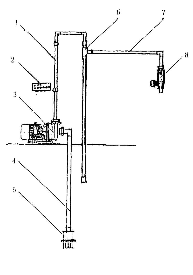
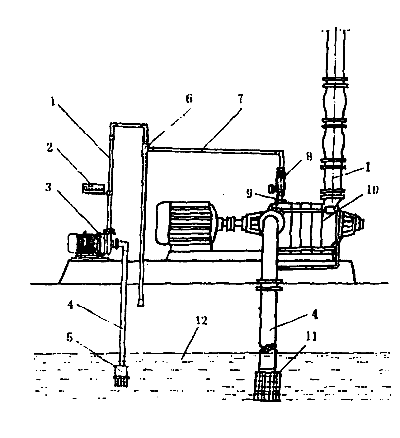
[0021] The dynamic operation of the present invention is described in conjunction with accompanying drawing:

[0022] Attached below Figure 5 A general description of the dynamic operation of the water jet vacuum pump: as Figure 5 As shown, the pressure water flow delivered by the water pipe 1 is sprayed into a high-speed water flow through the nozzle 27, and the high-speed water flow is discharged through the inner cavity of the pump body 28, the throat pipe 29, and the diffuser tube 30, and the high-speed water flow flows through the inner cavity of the pump body 28. During the process, the inner cavity of the pump body 28 is vacuumed, and the extracted gas is pressed into the inner cavity of the pump body 28 through the vacuum pipeline 7 and the suction port 31 and is carried by the high-speed water flow. After the gas carried by the high-speed water flow passes through the throat pipe 29, It is mixed with the water flow in the diffuser pipe 30 and discharged into the at...


PUM


Abstract

The invention relates to a full automatic vacuum suction piloting device which aims to remove the bottom valve of the water pump. The operation of the water pump without the bottom valve can realize energy conservation, enhance the pump efficiency, increase the suction lift of the water pump and prolong the service life of the water pump. The automatic vacuum suction device mainly comprises a motor direct-connected small-diameter large-lift-height centrifugal pump, a water flow ejector pump, a water level sensing and water flow cut-off device and an electric cabinet. The invention has the advantages of simple structure, small size, favorable properties, high automation degree, convenient installation and maintenance, and the like, and can be a general purpose standard facility for realizing water pump without bottom valve.

Description

1. Technical field [0001] The water pump water diversion vacuum automatic suction device of the present invention is a kind of automatic vacuum suction water diversion system device provided for the water pump to remove undercutting and save energy. 2. Background technology [0002] The water pump is a general-purpose equipment with a large number of applications. Before the pump is running, the pump chamber must be filled with water. To fill the water, a bottom cutting should be installed at the bottom of the suction pipe of the pump. Often, the bottom cutting is not tightly sealed. If the water pump cavity is not filled with diversion water, the water pump cannot be started and operated. The bottom felling is not only difficult to maintain but also causes resistance, reduces the efficiency of the water pump, reduces the suction lift of the water pump, wastes energy, and affects the service life of the water pump. [0003] The State Council listed the bottomless water pump ...

Claims


Application Information

Patent Timeline
Patent Type & Authority Patents(China)
IPC IPC(8): F04D9/06
Inventor 张庆玉穆玉芳
Owner 张庆玉
Learn More