Manual surface type biogas discharge pump
A discharge pump, surface-type technology, applied in the field of manual surface-type biogas discharge pump, can solve the problems of anti-blocking and unsatisfactory passing performance, anti-blocking performance is not as good as that of piston pumps, low manufacturing accuracy and suction lift requirements, etc. To achieve the effect of compact structure, not easy to jam, and stable pressure
- Summary
- Abstract
- Description
- Claims
- Application Information
AI Technical Summary
Problems solved by technology
Method used
Image
Examples
Embodiment 1
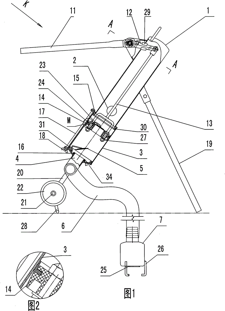
[0020] The manual ground type biogas discharge pump consists of: an upper pump body 1, the lower side of the upper pump body is provided with a liquid outlet pipe 2, the lower side of the upper pump body is connected to a cylinder liner 3, and the cylinder Connect the liquid inlet pipe 4 below the sleeve, the liquid inlet pipe is connected to the one-way valve 5, the liquid inlet pipe is connected to the suction pipe 6, and the liquid suction pipe is connected to the liquid suction head 7 with a one-way valve, The upper end of the upper pump body is connected to a discharge device, and the discharge device is connected to a piston 14 .
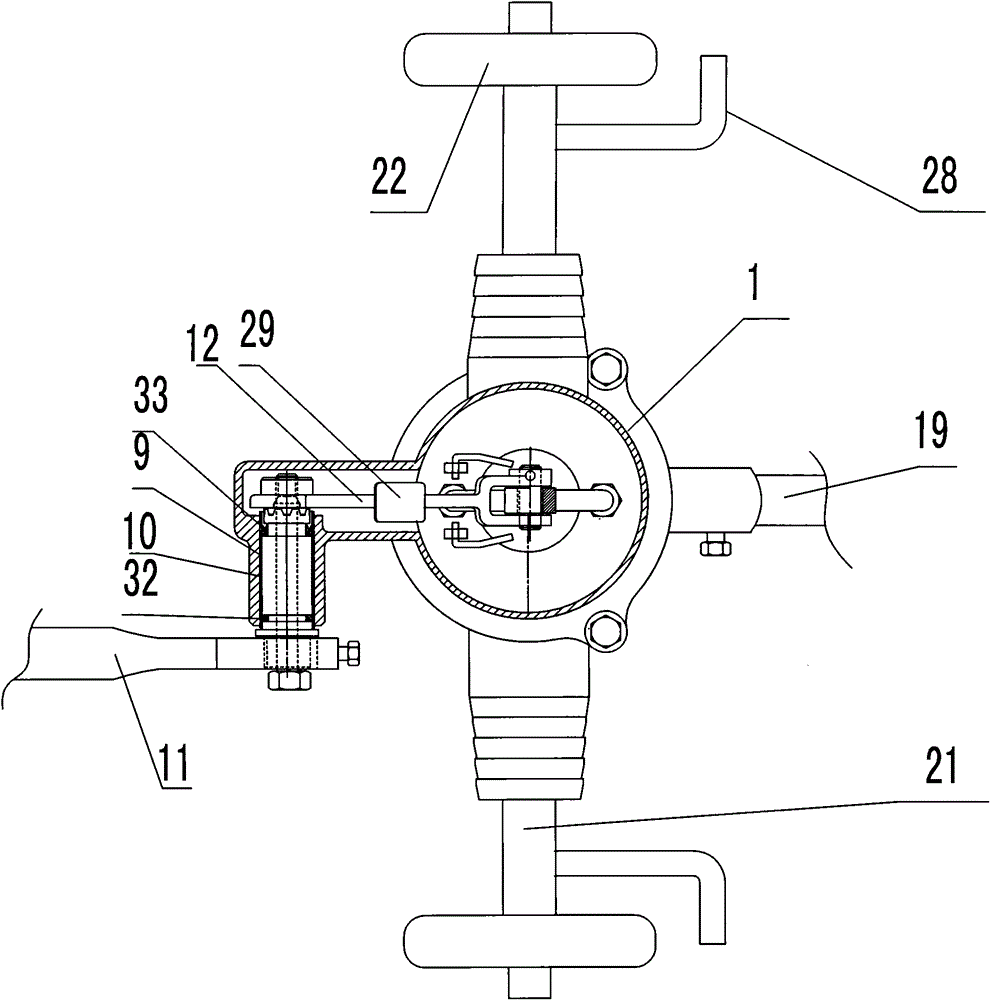
[0021] The discharge device includes 9, a drive shaft 10 is installed in the bushing, one end of the drive shaft is connected to a pressure handle 11, and the other end of the drive shaft is connected to a lever 12, and the lever and the piston The rod 13 is hinged, and the piston rod is connected to the piston 14 .
Embodiment 2
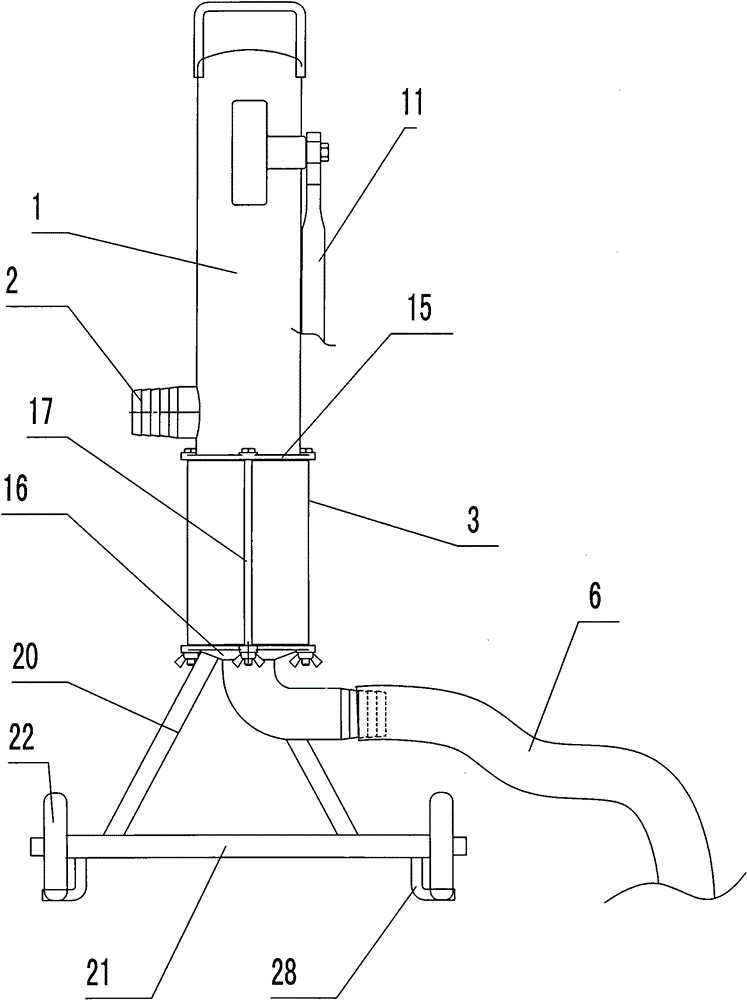
[0023] In the manual ground type biogas discharge pump described in Embodiment 1, the lower end of the upper pump body has an upper flange 15, the lower end of the cylinder liner is connected to the lower flange 16, and the upper flange is connected to the lower flange 16. The lower flanges are fastened by screw rods 17 and nuts 18, and the liquid inlet pipe is installed on the lower flanges.
Embodiment 3
[0025] For the manual ground type biogas discharge pump described in the above embodiment, there is a bracket under the pump body, and the bracket includes a support rod 19 installed on the upper pump body and a support rod connected to the lower flange. Legs 20, the lower ends of the supporting legs are fixed to the wheel shaft 21, casters 22 are installed at both ends of the wheel shaft, legs 28 are respectively provided at the two ends of the wheel shaft and the inner side of the caster wheels. The strut supports the pump body obliquely in a "herringbone" shape so that the resultant force of the pressing force and the center of gravity of the pump does not exceed the support point.
PUM
 Abstract
Description
Claims
Application Information
 - R&D
- Intellectual Property
- Life Sciences
- Materials
- Tech Scout
- Unparalleled Data Quality
- Higher Quality Content
- 60% Fewer Hallucinations
Browse by: Latest US Patents, China's latest patents, Technical Efficacy Thesaurus, Application Domain, Technology Topic, Popular Technical Reports.
© 2025 PatSnap. All rights reserved.Legal|Privacy policy|Modern Slavery Act Transparency Statement|Sitemap|About US| Contact US: help@patsnap.com


