Bias collision device and automobile with same

A technology for offset collisions and automobiles, which is applied to vehicle components, transportation and packaging, and upper structures, and can solve problems such as poor anti-offset collision capabilities, and achieve the effects of reducing collision deformation, reducing personal injuries, and improving performance

Inactive Publication Date: 2011-03-02
CHERY AUTOMOBILE CO LTD
View PDF4 Cites 8 Cited by
  • Summary
  • Abstract
  • Description
  • Claims
  • Application Information

AI Technical Summary

Problems solved by technology

[0007] In order to overcome the defect of poor anti-offset collision ability of existing domestic automobiles, the embodiment of the present invention provides an off-set collision device and a vehicle equipped with the device.

Method used


Image

  • Bias collision device and automobile with same
  • Bias collision device and automobile with same
  • Bias collision device and automobile with same

Examples


Embodiment 1

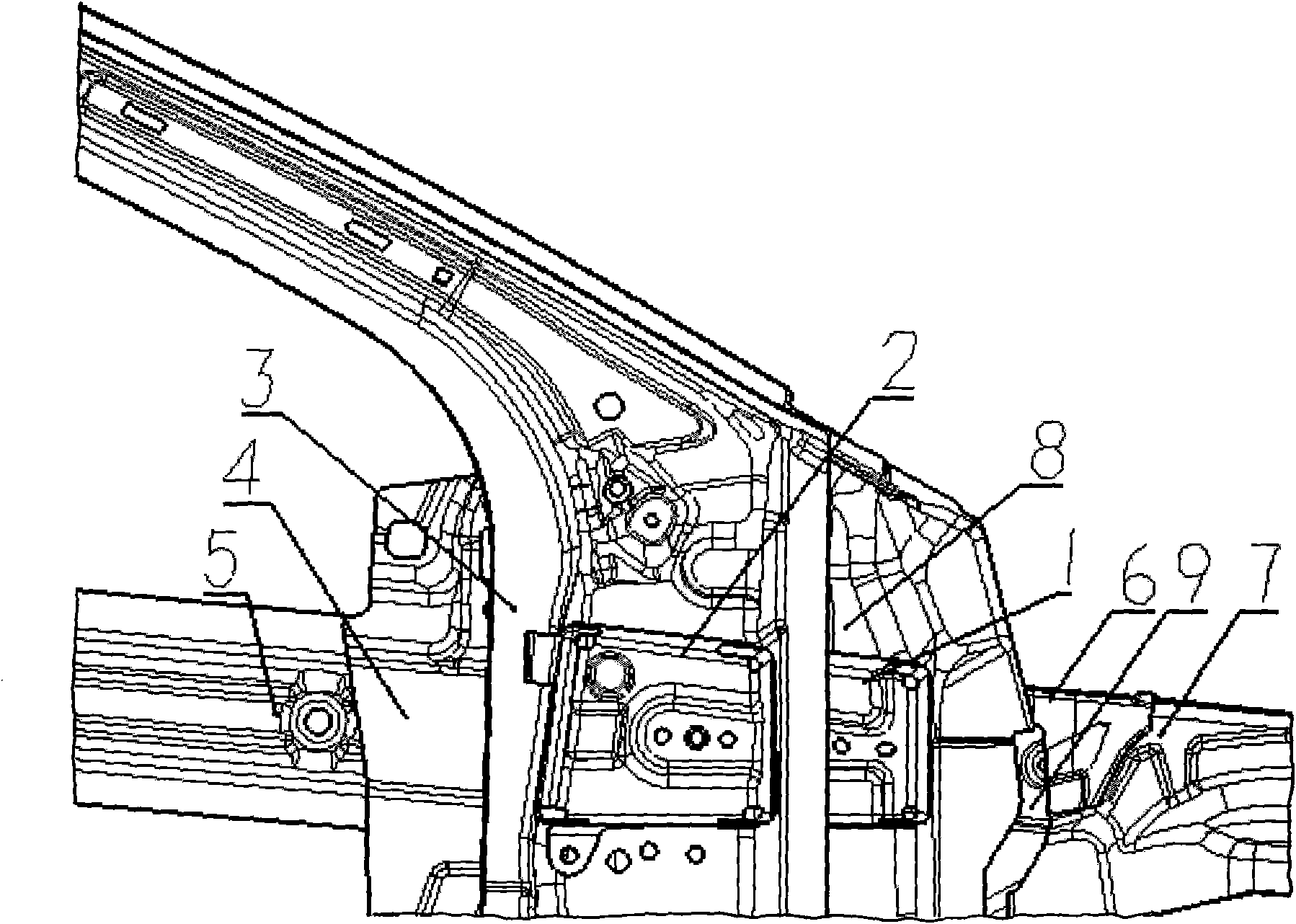
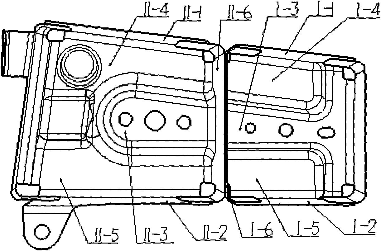
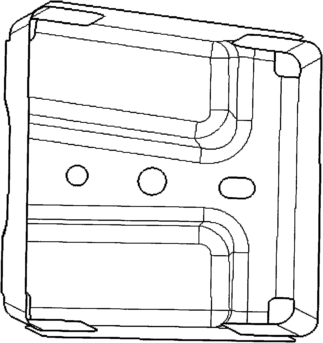
[0029] Such as figure 1 As shown, an offset collision device provided by the embodiment of the present invention is arranged at the A-pillar reinforcement panel 3, and the offset collision device includes a 8 connected box I 1, and box II 2 fixedly arranged inside the A-pillar reinforcement plate 3, the box I 1, the box II 2 and the A-pillar reinforcement plate 3 are connected as a whole, so that after the offset collision Part of the generated energy is transmitted along the window frame reinforcement plate 5 to the rear of the vehicle body.

[0030] Compared with the existing technology, during the collision process of the structure at the A-pillar of the side wall of the vehicle body, the collision energy can only be transmitted to the rear of the vehicle body through two lines, that is, the first line is transmitted to the rear of the vehicle body through the upper section of the A-pillar and the side beam ; and the second line, which is passed to the rear of the vehicle ...

Embodiment 2

[0041] see figure 1 , the present invention also provides an automobile with an offset collision device, including A-pillar reinforcement panels 3 respectively arranged on both sides of the vehicle body, each of the A-pillar reinforcement panels 3 is provided with an offset collision device, each Each of the offset collision devices includes a box I 1 fixedly arranged at the front of the A-pillar reinforcement panel 3 and connected to the side wall outer panel 8, and a box II 2 fixedly arranged inside the A-pillar reinforcement panel 3, the box I 1. The box II 2 and the A-pillar reinforcing plate 3 are integrated so that part of the energy generated after the offset collision is transmitted along the window frame reinforcing plate 5 to the rear of the vehicle body.

[0042] By applying the offset collision device of the present invention, a collision energy transmission line is added. Specifically, see figure 1 , in the event of a collision, part of the collision energy tran...


PUM


Abstract

The invention discloses a bias collision device and an automobile with the same, and belongs to the field of automobiles. The bias collision device comprises a box I and a box II, wherein the box I is fixedly arranged on the front part of an A column reinforced plate and is connected with side wall outer plate, and the box II is fixedly arranged in the A column reinforced plate. The automobile comprises A column reinforced plates, wherein the A column reinforced plates are respectively arranged on both sides of an automobile body, and each A column reinforced plate is provided with the bias collision device. In the embodiment of the invention, the boxes I and boxes II are respectively arranged and fixed on the A column reinforced plates on the two sides, and the boxes I, the boxes II and the A column reinforced plates are connected into a whole, so that part of the energy generated by bias collision is transferred to the rear part of the automobile body along the window frame reinforced plates, thereby effectively reducing the collision deformation of A columns and a doorsill, effectively improving the bias collision properties, relieving the injury of the bias collision on the people in the automobile, and finally satisfying the requirement of 40% bias collision at the speed of 64 km/h in the Europe new car assessment program (E-NCAP).

Description

technical field [0001] The invention relates to the field of automobiles, in particular to an offset collision device and an automobile with the device. Background technique [0002] Automobile safety performance testing has not only become a national standard and a hot spot in the industry, but also an important means of market promotion for automakers. [0003] NCAP is currently the standard basis for safety testing in various countries. NCAP first appeared in the United States in 1978. After entering the 1990s, Europe and Japan also successively established their own NCAP systems, which are called E-NCAP in Europe and J-NCAP in Japan. Among them, E-NCAP in Europe is the most influential and representative. [0004] China's C-NCAP test includes three items, one is the frontal 100% overlapping barrier crash test, the speed is not lower than 50 kilometers per hour; the other is the frontal 40% overlapping deformable barrier crash test, the speed is not lower than 56 kilome...

Claims


Application Information

Patent Timeline
Patent Type & Authority Applications(China)
IPC IPC(8): B62D25/04B62D25/16
Inventor 陈杰章强袁堂福时西芳
Owner CHERY AUTOMOBILE CO LTD
Why Eureka
Try Eureka