
Novel method for triggering and monitoring thyristors of direct-current converter valve

A technology of DC converter valve and thyristor, applied in the direction of output power conversion device, electrical components, etc., can solve the problem of complex pulse coding, and achieve the effect of simple triggering and monitoring methods

Inactive Publication Date: 2011-03-02
CHINA ELECTRIC POWER RES INST +1
View PDF2 Cites 6 Cited by
  • Summary
  • Abstract
  • Description
  • Claims
  • Application Information

AI Technical Summary

Problems solved by technology

[0003] The main disadvantages of the five-pulse method are passive monitoring of the thyristor state and complex pulse coding. After the valve-based electronic equipment sends the first trigger pulse to the thyristor trigger and monitoring unit, the state monitoring of the thyristor is between the second single pulse and the third single pulse. stage, at this stage, if the thyristor is normal, the thyristor trigger and monitoring unit sends a single pulse to the valve base electronics
[0005] At present, there is no similar technical patent at home and abroad

Method used


Image

  • Novel method for triggering and monitoring thyristors of direct-current converter valve
  • Novel method for triggering and monitoring thyristors of direct-current converter valve
  • Novel method for triggering and monitoring thyristors of direct-current converter valve

Examples


Embodiment Construction

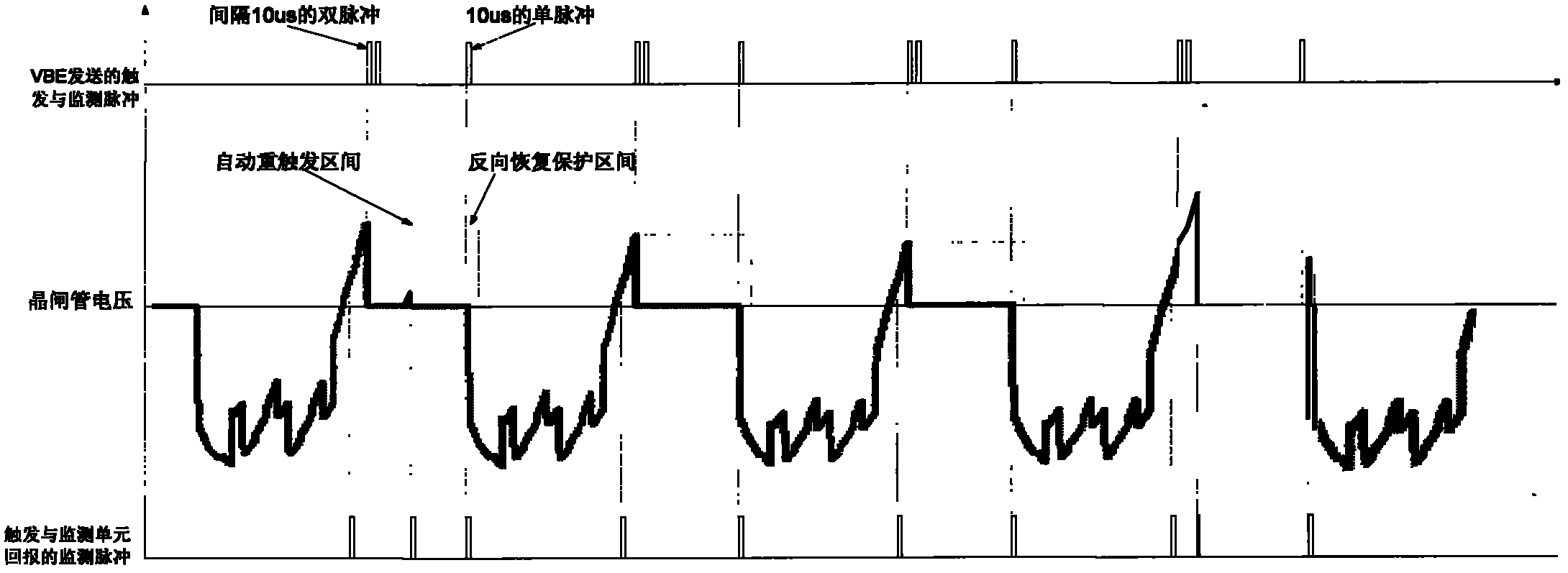
[0022] attached figure 1 Among them, the first double pulse represents the trigger pulse. After the thyristor trigger monitoring unit receives the double pulse, it triggers the thyristor. The following three single pulses are the monitoring pulses. The interval between the first single pulse and the double pulse is the thyristor overvoltage protection interval. , if the valve-based electronic equipment receives a return pulse in this interval, it means the thyristor overvoltage protection action; between the second single pulse and the third single pulse is the thyristor state monitoring stage, if the valve-based electronic equipment receives a return pulse in this interval The return pulse means that the state of the thyristor is normal; the third single pulse is the optical channel monitoring, and if the optical channel is normal, the thyristor triggering and monitoring unit sends a return pulse after receiving this pulse.

[0023] A novel DC converter valve thyristor trigge...


PUM


Abstract

The invention relates to a novel method for triggering and monitoring thyristors of a direct-current converter valve, which belongs to the electrical and electronic fields and the direct current transmission field. The method is implemented by thyristor triggering and monitoring units and a valve-based electronic device. The method comprises the following steps: after receiving wide-pulse triggering signals sent from an upper computer, the valve-based electronic device codes the wide-pulse triggering signals, and then sends the coded wide-pulse triggering signals to the thyristor triggering and monitoring units; after receiving trigger impulse codes, the thyristor triggering and monitoring unit decodes the trigger impulse codes, then triggers the thyristor, and returns corresponding states according to monitoring pulses of the valve-based electronic device, wherein the returning signals of the thyristor triggering and monitoring unit comprise the state of the thyristor, the states of protection actions, the working status of the thyristor triggering and monitoring unit, and the states of optical channels; the valve-based electronic device receives the returning signals of all thyristor triggering and monitoring units of the converter valve, monitors and records the state of the converter valve in real time, and reports the state of each thyristor level to the upper computer; and then the upper computer can display the state of each thyristor level in real time.

Description

technical field [0001] The invention belongs to the fields of electric power and direct current transmission, and relates to a novel thyristor triggering and monitoring method for a direct current converter valve. Background technique [0002] The triggering and monitoring of the traditional DC converter valve thyristor adopts a five-pulse method. figure 1 . The first double pulse represents the trigger pulse. After the thyristor trigger monitoring unit receives the double pulse, it triggers the thyristor. The next three single pulses are monitoring pulses. The interval between the first single pulse and the double pulse is the thyristor overvoltage protection interval. The valve-based electronic equipment receives a return pulse in this interval, which represents the thyristor overvoltage protection action; the period between the second single pulse and the third single pulse is the state monitoring stage of the thyristor, if the valve-based electronic equipment receives a...

Claims


Application Information

Patent Timeline
IPC IPC(8): H02M1/08H02M1/092
Inventor 张文亮王华锋温家良张娟
Owner CHINA ELECTRIC POWER RES INST
Learn More