
Non-navigable span pier collision avoidance monitoring system and real-time diagnosis method

A monitoring system and real-time diagnosis technology, applied in the testing of machine/structural components, measuring devices, impact testing, etc., can solve the problem of increased construction investment, uneconomical and uneconomical benefits, and the inability of non-navigation hole bridges to achieve collision avoidance with main navigation holes abilities, etc.

Active Publication Date: 2016-12-21
ZHEJIANG UNIV OF TECH
View PDF10 Cites 8 Cited by
  • Summary
  • Abstract
  • Description
  • Claims
  • Application Information

AI Technical Summary

Problems solved by technology

However, judging from the status quo of engineering, although countries around the world have adopted different anti-collision design concepts and methods, they cannot completely avoid the serious impact of ship collision with bridge accidents, especially in bridges with non-navigable holes in wide waters. Under severe weather conditions, the danger of bridge damage or destruction caused by the impact of large-tonnage ships still exists. According to the existing design concept, the design of bridges with non-navigable holes cannot achieve the same anti-collision capability as that of the main navigable holes. High-level anti-collision design for the entire line of the hole bridge will greatly increase the construction investment, which will be very uneconomical in terms of economy and benefits

Method used


Image

  • Non-navigable span pier collision avoidance monitoring system and real-time diagnosis method
  • Non-navigable span pier collision avoidance monitoring system and real-time diagnosis method
  • Non-navigable span pier collision avoidance monitoring system and real-time diagnosis method

Examples


Embodiment Construction

[0045] In order to enable those skilled in the art to better understand the solution of the present invention, the present invention will be further described in detail below in conjunction with the accompanying drawings and specific embodiments.

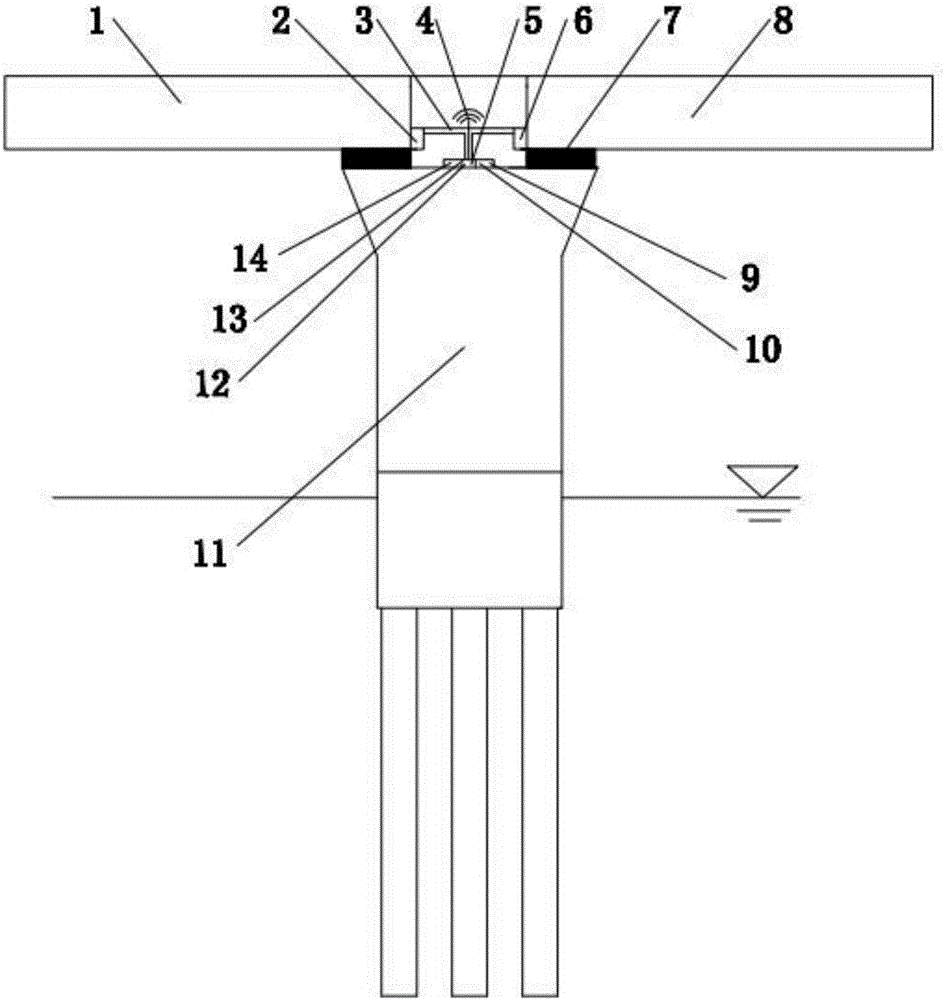
[0046] see figure 1 , a kind of anti-collision monitoring system of non-navigable piers of the present invention is installed on bridge A 1, bridge B 8 and bridge piers 11, and rubber bearings 7 are all provided between bridge A 1, bridge B 8 and bridge piers 11, Including sensor A2, sensor B6 and sensor 5 respectively arranged on bridge A1, bridge B 8 and pier 11, sensor A2, sensor B6 and sensor 5 are connected and fixed by T-shaped steel pipe 3 to form a T-shaped structure, sensor A2 and sensor B6 are installed The specific location is on the edge of the bridge deck of bridge A1 and bridge B8, the upper part of rubber bearing 7, close to bridge A1 and bridge B8, and the sensor 5 is installed on the top of bridge pier 11, which is ...


PUM


Abstract

The invention discloses a non-navigable span pier collision avoidance monitoring system and a real-time diagnosis method. The system comprises sensors mounted on a bridge A, a bridge B and a bridge pier respectively, a data acquisition instrument and a data denoising instrument and the like. The monitoring system can realize online real-time monitoring of bridge pier ship collision, can directly and quickly carry out preliminary judgment on bridge damage degree in the first time of bridge pier ship collision, and can directly analyze impact force and important bridge pier structure reaction parameters and provide first-hand data support for bridge operation close, immediate maintenance decision, bridge pier component state assessment and damage identification; the monitoring system is reasonable in design principle, light in structure and high in impact force identification precision; the whole monitoring system is low in cost, and can be largely applied to the cross-sea and cross-river bridges without increasing engineering construction cost too much, thereby solving the problem of high cost of omnibearing collision avoidance monitoring; and the monitoring system is high in engineering applicability.

Description

technical field [0001] The invention belongs to the technical field of bridge pier monitoring, and in particular relates to a monitoring system and a real-time diagnosis method for bridge pier anti-collision. Background technique [0002] The international systematic research on the problem of ship collision with bridges began in the early 1980s, and then domestic and foreign scholars carried out a lot of research in the field of ship collision risk analysis and ship bridge impact force, and put forward the bridge anti-collision risk assessment for design method and impact force value method, and began to formulate relevant design specifications. In 1991, the American Association of Highway Engineers (AASHTO) published the first design guidelines for bridges subjected to ship impact. Since the 1990s, with the construction of large-scale cross-sea bridges, scholars at home and abroad have carried out a large number of bridge anti-collision technology researches based on the ...

Claims


Application Information

Patent Timeline
IPC IPC(8): G01M7/08
CPCG01M7/08
Inventor 郭健朱绪江赵钦甘伟昌
Owner ZHEJIANG UNIV OF TECH
Learn More