Transmission line travelling wave recording method

A transmission line and traveling wave technology, applied in the direction of the fault location, etc., can solve the problems of large amount of data uploaded by traveling wave signals, many false trigger waveforms, and undetectable traveling wave signals, etc., and achieve simple monitoring methods, high identification accuracy, The effect of reducing the number of waveform false triggers

Active Publication Date: 2013-08-07
GUIZHOU POWER GRID CO LTD
View PDF8 Cites 9 Cited by
  • Summary
  • Abstract
  • Description
  • Claims
  • Application Information

AI Technical Summary

Problems solved by technology

[0005] The purpose of this patent is to propose a traveling wave recording method for transmission lines to solve the problem that the traditional waveform monitoring method based on threshold value triggering is relatively weak when dealing with monitoring high-impedance grounding, and the traveling wave signal is often not detected. After purely reducing the trigger threshold of traveling wave monitoring, there will be a large amount of uploaded data, many false trigger waveforms, and difficult identification and screening of fault waveforms. At the same time, it will also cause the life of the monitoring terminal to decrease, the cost of data transmission to increase, and the difficulty of fault diagnosis. A series of problems such as increasing

Method used


Image

  • Transmission line travelling wave recording method
  • Transmission line travelling wave recording method
  • Transmission line travelling wave recording method

Examples


Embodiment Construction

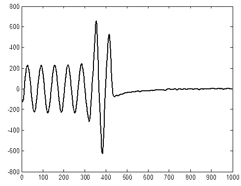
[0012] According to the sudden change of the power frequency current at the fault time, the method uses the fault component method to find out the accurate fault time, and extracts the waveform triggered and uploaded at the fault time in a short time. The principle is as follows:

[0013] The power frequency waveform is the 50Hz sinusoidal current waveform transmitted on the line that we currently use. When dealing with power frequency waveforms, we usually adopt the following basic assumptions:

[0014] (1) The power frequency waveform after filtering is an ideal smooth sinusoidal waveform.

[0015] (2) The frequency of the normal power frequency waveform will not change, which is 50Hz in China.

[0016] (3) The power frequency current will not change drastically when the line is running.

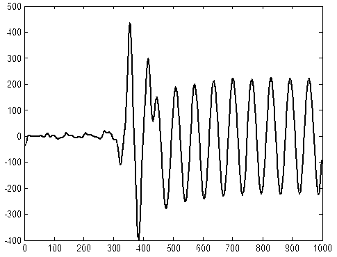
[0017] figure 1 It shows a waveform diagram of a faulty power frequency. The power frequency current suddenly rises at the time of the fault, and the current suddenly decreases at the t...


PUM


Abstract

The invention provides a transmission line travelling wave recording method and belongs to the technical field of electricity according to the classification of international patent classification (IPC) table. The problems that when the current waveform monitoring method based on threshold triggering is used for monitoring high-resistance ground, a travelling signal cannot be monitored due to being relatively weak, and after triggering threshold of travelling wave monitoring is purely reduced, uploaded data amount is large, error triggering waveforms are excessive in number, a fault waveform is difficultly identified and selected, and meanwhile the service life of a monitoring terminal is shortened, the data transmission cost is increased, and the fault diagnosis difficulty is increased are solved. Power-frequency fault monitoring and travelling wave fault monitoring are combined, fault moment information is accurately extracted according to waveform information in a power-frequency fault, and travelling wave current at the fault moment is accurately extracted, so that fault real-time wave recording of fault components is realized, and the identifying precision of the waveform is improved. The monitoring method is simple and small in waveform error triggering number, and has the characteristic of real-time online ability.

Description

technical field [0001] The invention relates to the field of fault location of transmission lines in power systems, in particular to the field of traveling wave fault location. Background technique [0002] Traveling wave fault location is an emerging fault location technology, in which whether the waveform at the time of the fault can be collected normally is an important link related to whether the traveling wave can be located. However, many high-impedance grounded traveling wave currents have the characteristics of small current amplitude and small difference from the interference traveling wave amplitude in the line, which brings great difficulties to traveling wave acquisition and identification. [0003] The current technology uses power frequency current and traveling wave current to trigger and capture respectively to obtain fault time information. This method has relatively poor resolution ability for relatively weak traveling wave signals. Therefore, it is diffi...

Claims


Application Information

Patent Timeline
Patent Type & Authority Applications(China)
IPC IPC(8): G01R31/08
Inventor 刘锐虢韬刘奕杨恒徐梁刚严尔梅吴兆鑫
Owner GUIZHOU POWER GRID CO LTD
Why Eureka
Try Eureka