A footstool

A footstool, anti-displacement technology, applied in footstools, stools, home appliances, etc., can solve the problems of separation, abnormally large weight, etc.

Inactive Publication Date: 2011-04-06
ABOLKHEIR GROUP
View PDF0 Cites 2 Cited by
  • Summary
  • Abstract
  • Description
  • Claims
  • Application Information

AI Technical Summary

Problems solved by technology

However, the weight of the feet and some of the weight of the legs will produce Pressure, plus any pressure from the foot-pushing will d

Method used


Image

  • A footstool
  • A footstool
  • A footstool

Examples


Example Embodiment

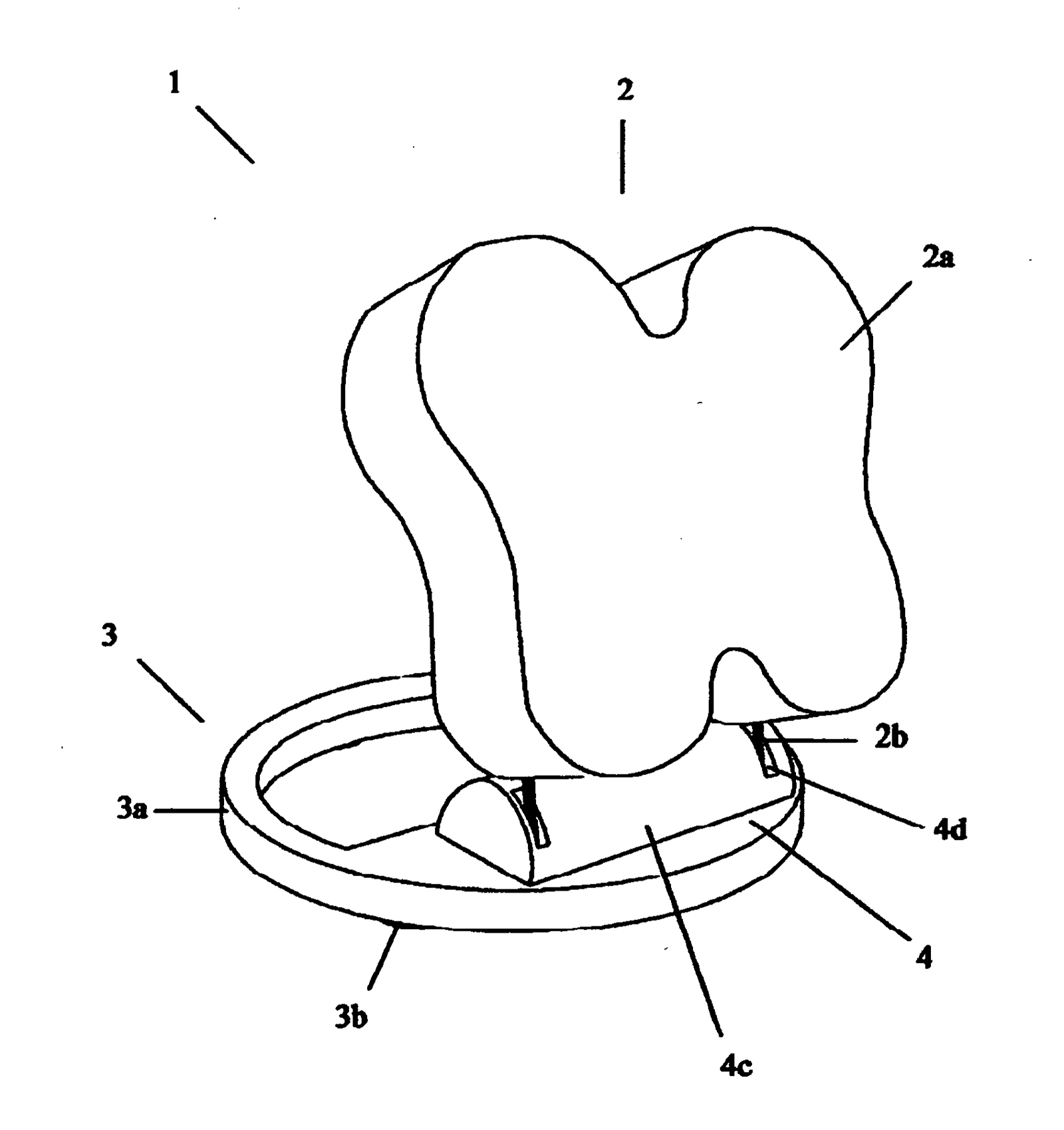
[0006] figure 1 It is a schematic diagram of a specific embodiment of the present invention. The footrest 1 in the figure includes a rotatable and movable sole-supporting surface 2 for supporting the sole of the foot, a base 3 supported by the ground, and a connecting device 4, wherein the The support surface 2 for supporting the sole of the foot includes a flat surface 2a and a movable arm (lever arms) 2b, the base 3 supported by the ground includes a platform 3a and a rubber support 3b, and the connecting device 4 is a protective cover hidden at the bottom 4c, the protective cover 4c is provided with a groove 4d, and the movable arm 2b can move freely in the groove 4d.

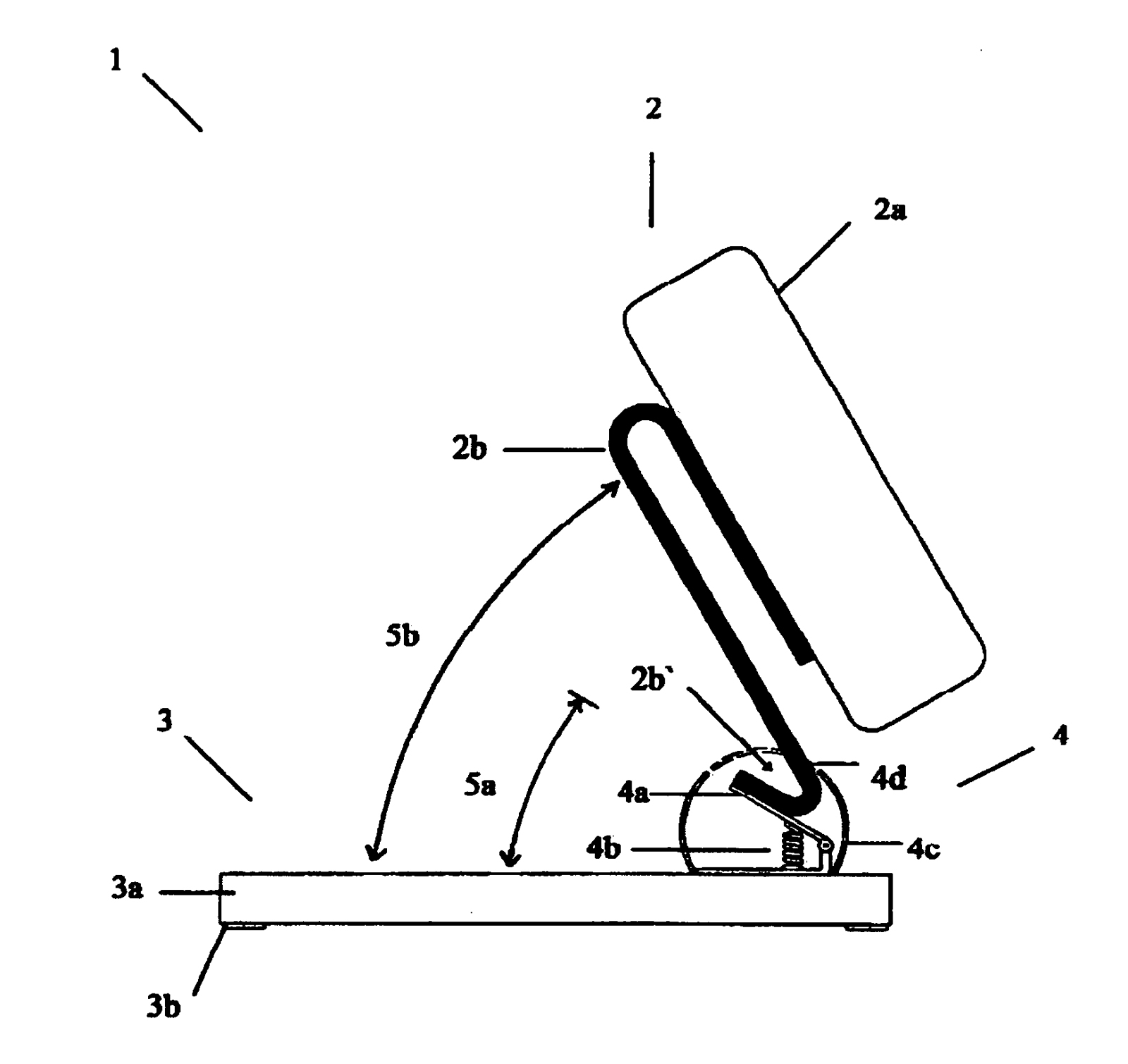
[0007] figure 2 for figure 1 Sectional view of the footrest in , wherein the connecting means 4 comprise a limited-travel hinge 4a and compression springs 4b, which only allow a range of motion of about 30°, as indicated by reference numeral 5a. figure 2 , the angle at which the bottom of the movable ...


PUM


Abstract

A displacement-resistant footstool (1) comprising a sole-supporting surface (2), a ground-supported base (3) and connecting means (4) that connects the sole-supporting surface (2) to the base (3) and substantially redirects the sole-released forces, which are generated by the weight of the feet and a proportion of the weight of the legs plus any additional foot-pushing forces from a substantially horizontal direction that points away from the person to a substantially vertically downward direction towards and pressing onto the floor. In effect substantially converting the sole-released forces from being displacement forces to being.

Description

technical field [0001] The invention relates to an anti-displacement footstool for supporting the sole of a foot. Background technique [0002] When sitting, people are usually used to contact the heel and / or the entire area extending from the heel to the back of the calf with the supporting surface of the footstool to form one or more contact points, so that the footstool supports both feet. Although this way is considered to be a more comfortable way of sitting, it can also cause a person's sitting posture to appear slouching and listless. [0003] Another way to support the feet is to use the soles of the feet as one or more points of contact with the support surface of the footstool, especially when the feet are slightly tilted so that the toes are higher than the heels, which helps eliminate slouching posture . However, the weight of the feet and some of the weight of the legs will produce The pressure, plus any pressure from the foot-pushing, will displace the suppo...

Claims


Application Information

Patent Timeline
IPC IPC(8): A47C16/02
CPCA47C16/02
Inventor M·H·阿博尔克海尔
Owner ABOLKHEIR GROUP
Why Eureka
Try Eureka