
Automobile body structure on lower part of automobile with moveable top

A technology of movable roof and body, applied in the substructure, vehicle parts, transportation and packaging, etc., can solve the problems of insufficient strength and rigidity of non-cage body, and achieve the effect of strengthening rigidity, local strength, and bending resistance.

Active Publication Date: 2011-04-20
CHERY AUTOMOBILE CO LTD
View PDF7 Cites 5 Cited by
  • Summary
  • Abstract
  • Description
  • Claims
  • Application Information

AI Technical Summary

Problems solved by technology

[0004] The purpose of the present invention is to provide a movable roof automobile lower body structure to solve the problem of insufficient strength and rigidity of the non-cage body

Method used


Image

  • Automobile body structure on lower part of automobile with moveable top
  • Automobile body structure on lower part of automobile with moveable top

Examples


Embodiment 1

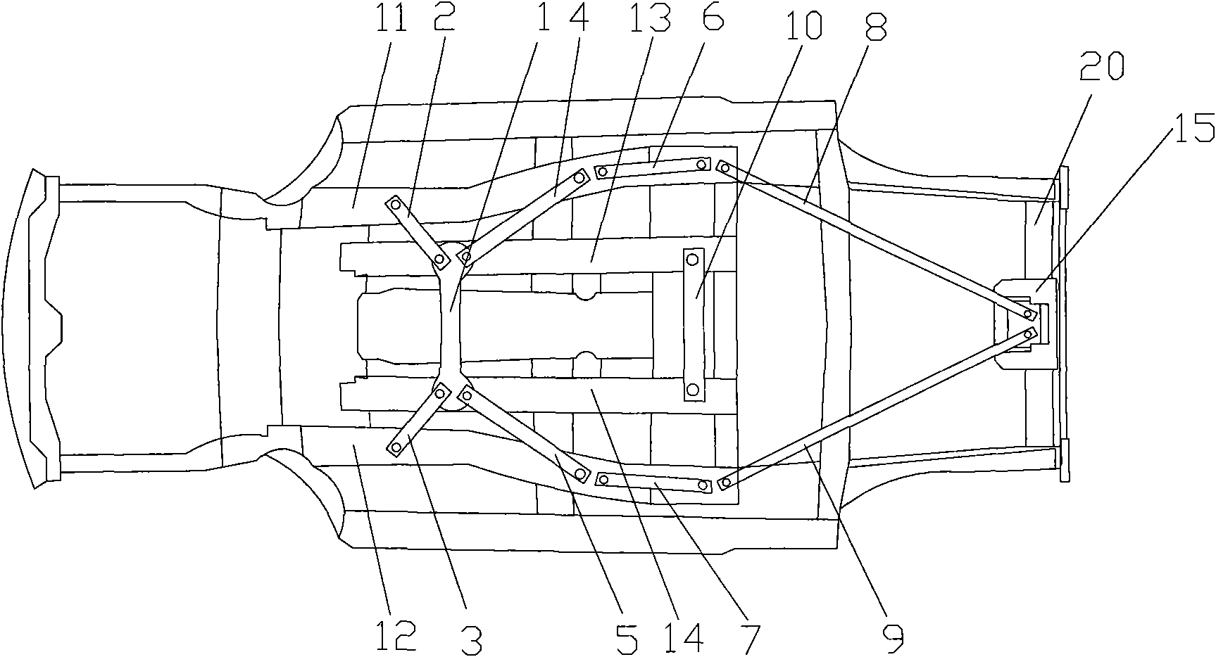
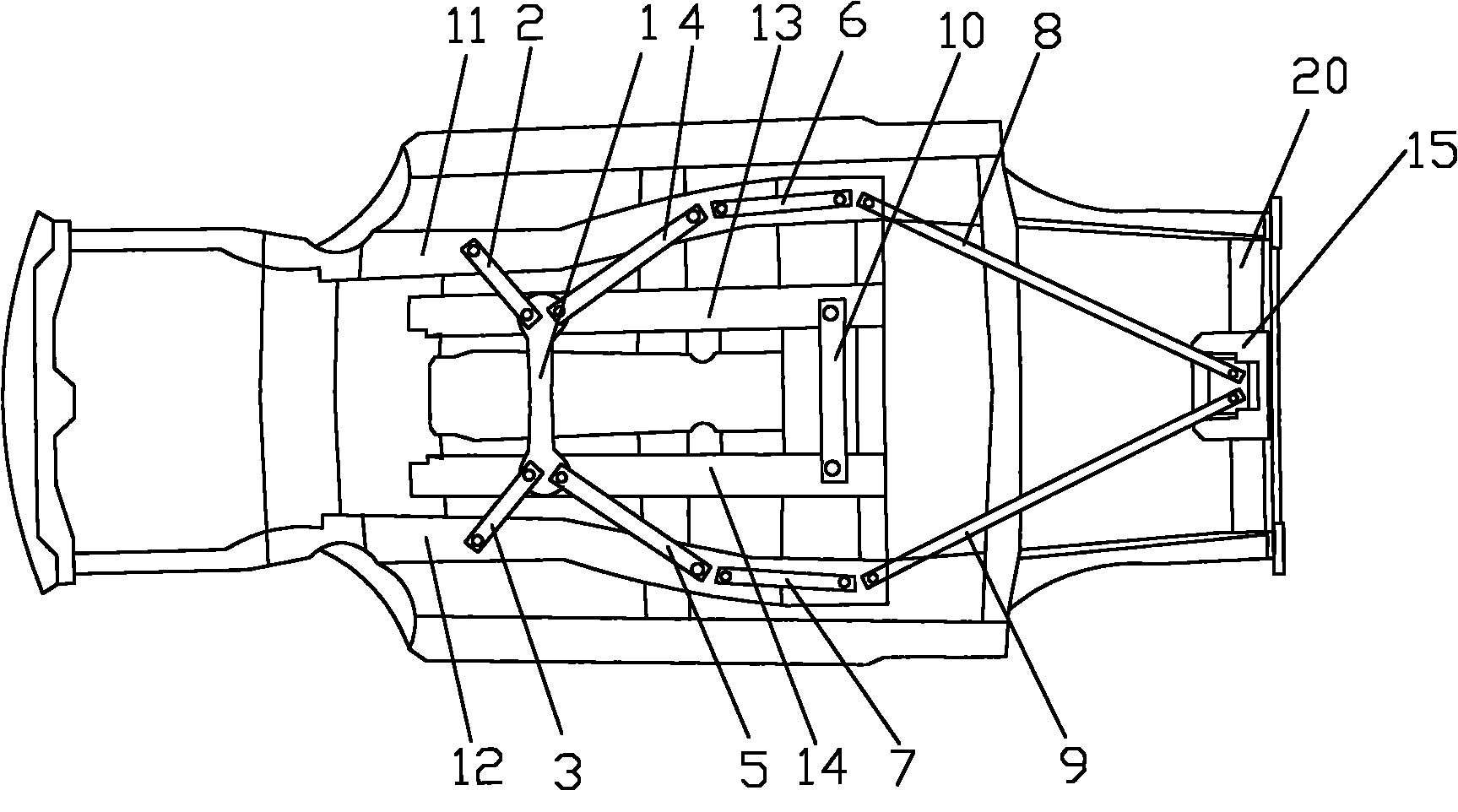
[0012] Example 1, as figure 1 As shown, a lower body structure of an automobile with a movable roof includes a left longitudinal beam 11 and a right longitudinal beam 12. The left and right longitudinal beams are symmetrically distributed on both sides of the vehicle body, and are arranged on the rear cross beam 20 at the rear end of the vehicle body; The inner side is also symmetrically provided with a left inner longitudinal beam 13 and a right inner longitudinal beam 14, and a reinforcing beam 1 is arranged between the front ends of the two inner longitudinal beams; A set of inclined support plates, including a first inclined support plate 2, a second inclined support plate 4, one end of the two inclined support plates are respectively fixed on the left longitudinal beam 11, and the other ends are respectively at the position of the reinforcing beam 1 and the left inner longitudinal beam 13. connected to form a triangular structure. A second group of oblique support plates...

Embodiment 2

[0013] Embodiment 2, on the basis of the technical solution of Embodiment 1, a fifth support plate 8 is further arranged between the rear cross beam 20 and the left longitudinal beam 11 , and between the rear cross beam 20 and the right longitudinal beam 12 A sixth support plate 9 is also provided. In order to facilitate the fixing of the fifth support plate 8 and the sixth support plate 9, a bracket 15 is provided in the middle of the rear cross member 20, and the fifth support plate 8 is fixedly connected between the bracket 15 and the left longitudinal beam 11. The support plate 9 is fixedly connected between the bracket 15 and the right longitudinal beam 12, and the fifth support plate 8 and the sixth support plate 9 are arranged in a V-shape, which can well enhance the rigidity of the rear end of the vehicle body.

Embodiment 3

[0014] Embodiment 3, on the basis of the technical solution of Embodiment 1 or Embodiment 2, a first support plate 6 is provided at the longitudinal middle position of the left longitudinal beam 11, and the support plate 6 is located between the second inclined support plate 4 and the first support plate 6. The five support plates 8 are between the fixed points on the left longitudinal beam 11 ; a second support plate 7 is provided at the position of the right longitudinal beam 12 corresponding to the first support plate 6 . The first support plate 6 and the second support plate 7 can enhance the bending resistance of the whole vehicle, and will not cause an obvious weak area in the middle of the vehicle under bending conditions, and when the entire front and rear directions are bent, the deformation is relatively evenly.


PUM


Abstract

An automobile body structure on the lower part of an automobile with a moveable top, comprises a left longitudinal beam, a right longitudinal beam, a left inner longitudinal beam and a right longitudinal beam and a strengthening beam, and a back cross beam disposed at a back end of the automobile, wherein a first group of inclined support plates are arranged between the left longitudinal beam and the left inner longitudinal beam; the first group of inclined support plates includes a first inclined support plate and a second inclined support plate, one ends of the first and the second inclined support plates are respectively fixed on the left longitudinal beam, and the other ends are connected to the left inner longitudinal beam at the strengthening beam position to form a triangle structure; a second group of inclined support plates are arranged between the right longitudinal beam and the right inner longitudinal beam; the second group of the inclined support plates includes a third inclined support plate and a fourth inclined support plate; one ends of the third and the fourth inclined support plates are respectively fixed on the right longitudinal beam, and the other ends are connected to the right longitudinal beam at the strengthening beam position to form one triangle structure. The automobile body structure of the invention solves the problem of low torsion rigidity of the lower part of the prior automobile with the moveable top, and the automobile body structure is simple. The automobile body structure can be widely applied to the lower automobile body with the moveable top.

Description

technical field [0001] The invention relates to an automobile body structure, in particular to a lower body structure of a movable roof automobile. Background technique [0002] Due to the development of the automobile industry, people are pursuing the use of automobiles and also further enjoying the visual beauty and driving pleasure brought by automobiles, resulting in more and more sports cars, especially sports cars with movable roofs. sought after by the younger generation. Due to the non-traditional body structure of the frame of the active roof car, the body stiffness cannot be shared by the floor assembly, the column, the front cabin, the roof, etc. like the traditional body structure, and most of the stiffness needs to be guaranteed by the floor. [0003] Therefore, the requirements for the beam structure of the underbody assembly will be increased accordingly, and it needs to be properly strengthened to meet the rigidity requirements of the entire body-in-white. ...

Claims


Application Information

Patent Timeline
IPC IPC(8): B62D21/02
Inventor 叶远林
Owner CHERY AUTOMOBILE CO LTD
Learn More