Method and apparatus for driving display panel
一种显示面板、设备的技术,应用在静态指示器、仪器等方向,能够解决大面积、消耗大电力、占用等问题
- Summary
- Abstract
- Description
- Claims
- Application Information
AI Technical Summary
Problems solved by technology
Method used
Image

Examples
no. 1 example
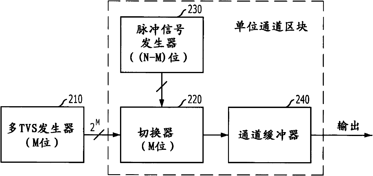
[0048] image 3 It is a block diagram illustrating a driver for a display panel using a multi-time-varying signal (TVS) generator and a common pulse signal generator according to a first embodiment of the present invention.
[0049] see image 3 , the driver includes a driver configured to generate multiple (2 M multiple time-varying signal (TVS) generator 310 of a) time-varying signal and is configured to generate multiple (2 TVS) generators with different pulse widths N-M a) common pulse signal generator 330 for the pulse signal. Moreover, the driver includes a selector 320 and a channel buffer 340 . Selector 320 receives the multiple (2 M a) time-varying signal, the multiple (2 N-M a) pulse signal and video data D to select the grayscale voltage corresponding to the video data. The channel buffer 340 outputs the output of the selector 320 to the source lines of the display panel. Herein, N and M are positive integers and N is greater than M (N>M). For each period of...
no. 2 example
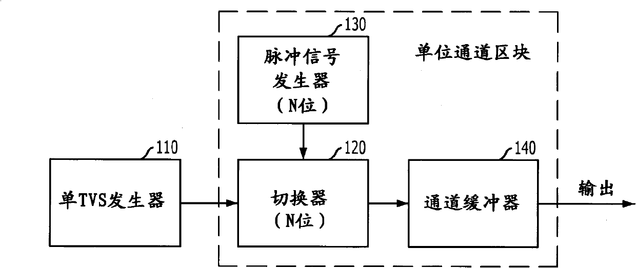
[0071] The first embodiment described above describes the use of multiple time-varying signals. Hereinafter, a second embodiment using a single time-varying signal will be described. As in the first embodiment, the second embodiment to be described hereinafter uses a common pulse signal generator. The common pulse signal generator includes a register for controlling the on / off time ratio of the pulse signal.
[0072] Figure 8 It is a block diagram illustrating a driver using a single TVS generator and a common pulse signal generator according to the second embodiment of the present invention.
[0073] see Figure 8 , the driver includes a single TVS generator 810 , a common pulse signal generator 830 , a selector 820 and a channel buffer 840 . Single TVS generator 810 generates a single time-varying signal. The common pulse signal generator 830 produces multiple (2 N a) pulse signal. The selector 820 receives the single time-varying signal, the plurality of pulse signa...
no. 3 example
[0086] In the first and second embodiments described above, the target grayscale voltage is determined based on the time-varying signal having a voltage value and the width of the pulse signal. However, in the third embodiment to be described hereinafter, the target grayscale voltage is determined based on a time-varying signal having a current value and the width of a pulse signal, and all other constituent elements and operations are the same.
[0087] Figure 11A For illustration shown in Figure 5 A block diagram of a modified example of a selector for a drive in .
[0088] see Figure 11A The TVS selection unit 426_1 includes a 1-bit decoding element 426A_1 , a voltage-to-current conversion (VCC) element 426C and a switching element 426B_1 .
[0089] The 1-bit decoding element 426A_1 selects and outputs one of the two voltage time-varying signals TVS_V and TVS_V based on the upper 1-bit data D obtained from the level shift unit 424 . The voltage-to-current converting ...
PUM
 Abstract
Description
Claims
Application Information
 - Generate Ideas
- Intellectual Property
- Life Sciences
- Materials
- Tech Scout
- Unparalleled Data Quality
- Higher Quality Content
- 60% Fewer Hallucinations
Browse by: Latest US Patents, China's latest patents, Technical Efficacy Thesaurus, Application Domain, Technology Topic, Popular Technical Reports.
© 2025 PatSnap. All rights reserved.Legal|Privacy policy|Modern Slavery Act Transparency Statement|Sitemap|About US| Contact US: help@patsnap.com