Projection image display device

A technology of image display and projection, which is applied in the direction of using projection device image reproducer, image communication, TV, etc., can solve the problem of poor operability of image distortion correction, and achieve the effect of improving operability

Inactive Publication Date: 2011-04-20
SANYO ELECTRIC CO LTD
View PDF5 Cites 14 Cited by
  • Summary
  • Abstract
  • Description
  • Claims
  • Application Information

AI Technical Summary

Problems solved by technology

[0007] When using the projector disclosed in Patent Document 1 above, when the image distortion is corrected by key operation, it is difficult for the user to visually recognize the distortion of the projected image displayed on the screen when the image signal is not clear. , so the operability of image distortion correction is poor

Method used


Image

  • Projection image display device
  • Projection image display device
  • Projection image display device

Examples


Embodiment approach 1

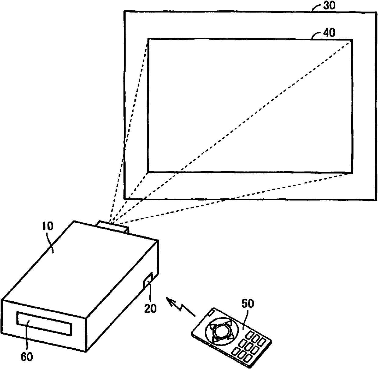
[0033] figure 1 It is a schematic configuration diagram of the projection type image display device according to Embodiment 1 of the present invention.

[0034] refer to figure 1 The projection-type video display device (hereinafter also referred to as "projector") 10 according to Embodiment 1 is a liquid crystal projector for projecting images by using a liquid crystal device. 30 to display the projected image 40 . The projection surface is not limited to the screen 30, and may be a wall surface.

[0035] The projector 10 includes: a remote control receiving unit 20 that receives an infrared-modulated remote control signal transmitted from a remote controller (abbreviation of remote controller) 50 operated by a user; and an input unit 60 . The remote control signal includes a command signal for remotely controlling the projector 10 . The input unit 60 includes an input port for receiving video signals supplied from an external signal supply device (not shown). The sign...

Embodiment approach 2

[0088] refer to Figure 8 The switching control process of the display color of the correction pattern in the image distortion correction process according to the second embodiment will be described.

[0089] refer to Figure 8 The display color switching in Embodiment 2 is performed by switching (toggle-shaped) among a plurality of preset colors every fixed time. exist Figure 8 In this example, the display colors of the correction patterns are switched every fixed time T in the order of white, red, and blue.

[0090] Figure 9 It is a flowchart illustrating display color switching control processing in the second embodiment. In addition, by executing a program previously stored in the microcomputer 70, it is realized Figure 9 The processing of each step.

[0091] refer to Figure 9 , according to the processing flow of Embodiment 2 and Image 6 The only difference in the flow chart is that steps S02 to S05 are changed to steps S22 to S24.

[0092] exist Figure 9 ...

Embodiment approach 3

[0102] refer to Figure 11 The switching control process of the display color of the correction pattern in the image distortion correction process according to the third embodiment will be described.

[0103] Figure 11 It is a flowchart illustrating display color switching control processing in the third embodiment. In addition, by executing a program previously stored in the microcomputer 70, it is realized Figure 11 The processing of each step.

[0104] refer to Figure 11 , according to the processing flow of Embodiment 3 and Image 6 The only difference in the flow chart is that steps S02 to S05 are changed to steps S31 to S34.

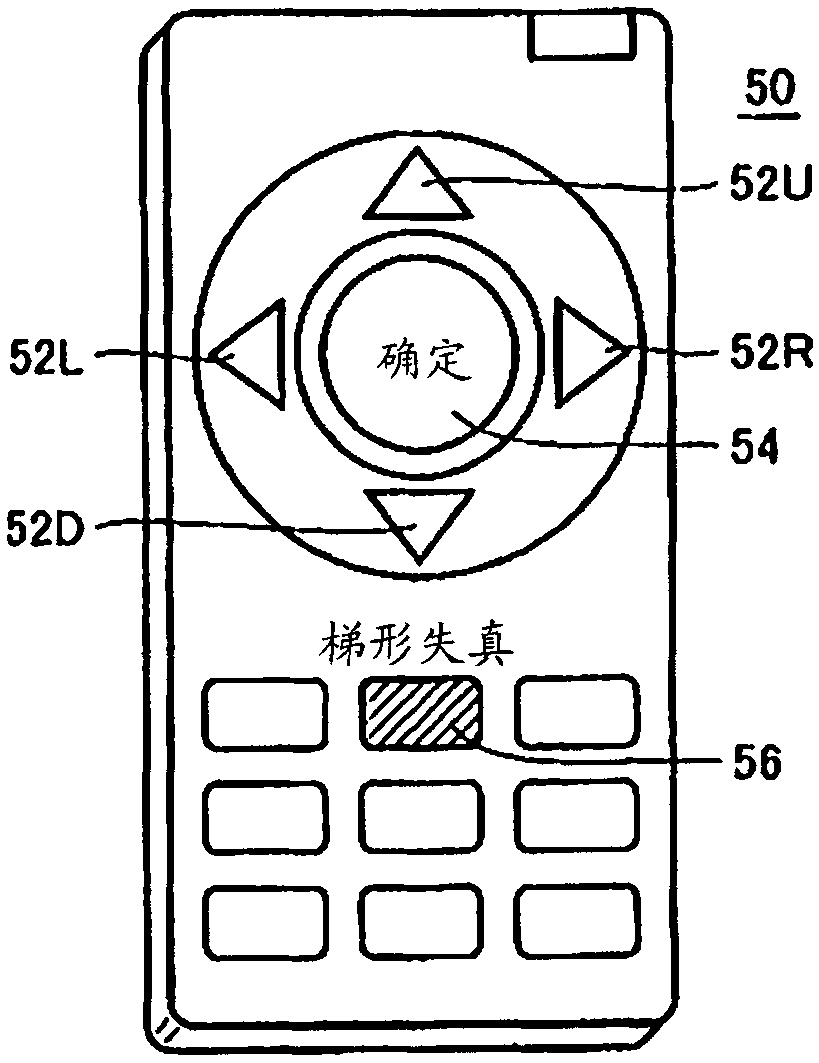
[0105] exist Figure 11 First, the microcomputer 70 judges whether or not the Keystone remote control button 56 is operated (pressed) based on the remote control signal received by the remote control receiver 20 (step S01). When it is determined that the Keystone remote control button 56 has not been operated ("No" in determination S01), th...


PUM


Abstract

A projector (10) includes: an image signal processing circuit (64) which receives and converts a first image signal to generate a second image signal representing an image to be projected; an image distortion correction unit (68) which corrects the second image signal in response to a correction point on a projected image being changed by an operation done by a user; and an OSD circuit (72) which operates, in response to an image distortion correction process being selected in response to an operation done by the user, to superpose a correction pattern used to allow the user to designate the correction point on the projected image, and thus display the correction pattern and the projected image on a single screen. The OSD circuit (72) includes a switching control unit which switches a color used to display the correction pattern when the image distortion correction process is performed.

Description

technical field [0001] The present invention relates to a projection-type image display device, and more specifically, to a projection-type image display device having a function of correcting distortion of an image displayed on a projection surface. Background technique [0002] In a projection-type image display device (hereinafter, also referred to as a projector), sometimes due to the relative inclination between the optical axis of the projection light from the projector and the projection surface such as a screen, the image projected on the projection surface may not be horizontal. The so-called image distortion that deforms in at least one of the horizontal and vertical directions. [0003] Usually, a correction function for correcting such image distortion is provided in the projector. For example, Japanese Unexamined Patent Publication No. 2008-79016 (Patent Document 1) discloses a configuration including a first keystone correction key for correcting the trapezoid...

Claims


Application Information

Patent Timeline
Patent Type & Authority Applications(China)
IPC IPC(8): H04N5/74H04N9/31
CPCH04N9/3185H04N9/3197H04N9/76H04N21/485
Inventor 藤崎刚海濑直纪儿玉和则
Owner SANYO ELECTRIC CO LTD
Why Eureka
Try Eureka