Dual Seat Valve

Inactive Publication Date: 2016-05-05
ENGIP LLC
View PDF25 Cites 0 Cited by
  • Summary
  • Abstract
  • Description
  • Claims
  • Application Information

AI Technical Summary

Benefits of technology

[0008]The plunger has a second valve surface that engages a second seat in the valve body. As the valve is opened, the piston initially separates from the first valve seat while the plunger piston still engages the second valve seat. As the piston is further moved away from the valve seats, the second valve surface disengages from the second valve seat. The first valve seat is an elastomeric ring member. Thus as the valve is opened, the piston disengag

Problems solved by technology

Valves using highly polished seat assemblies, can be made to have very small leaks, but not “bubble tight.” Additionally these valves are very susceptible to damage of their highly polished seat assemblies.
This is a difficult requirement for most hydrostat

Method used


Image

  • Dual Seat Valve
  • Dual Seat Valve
  • Dual Seat Valve

Examples


Example

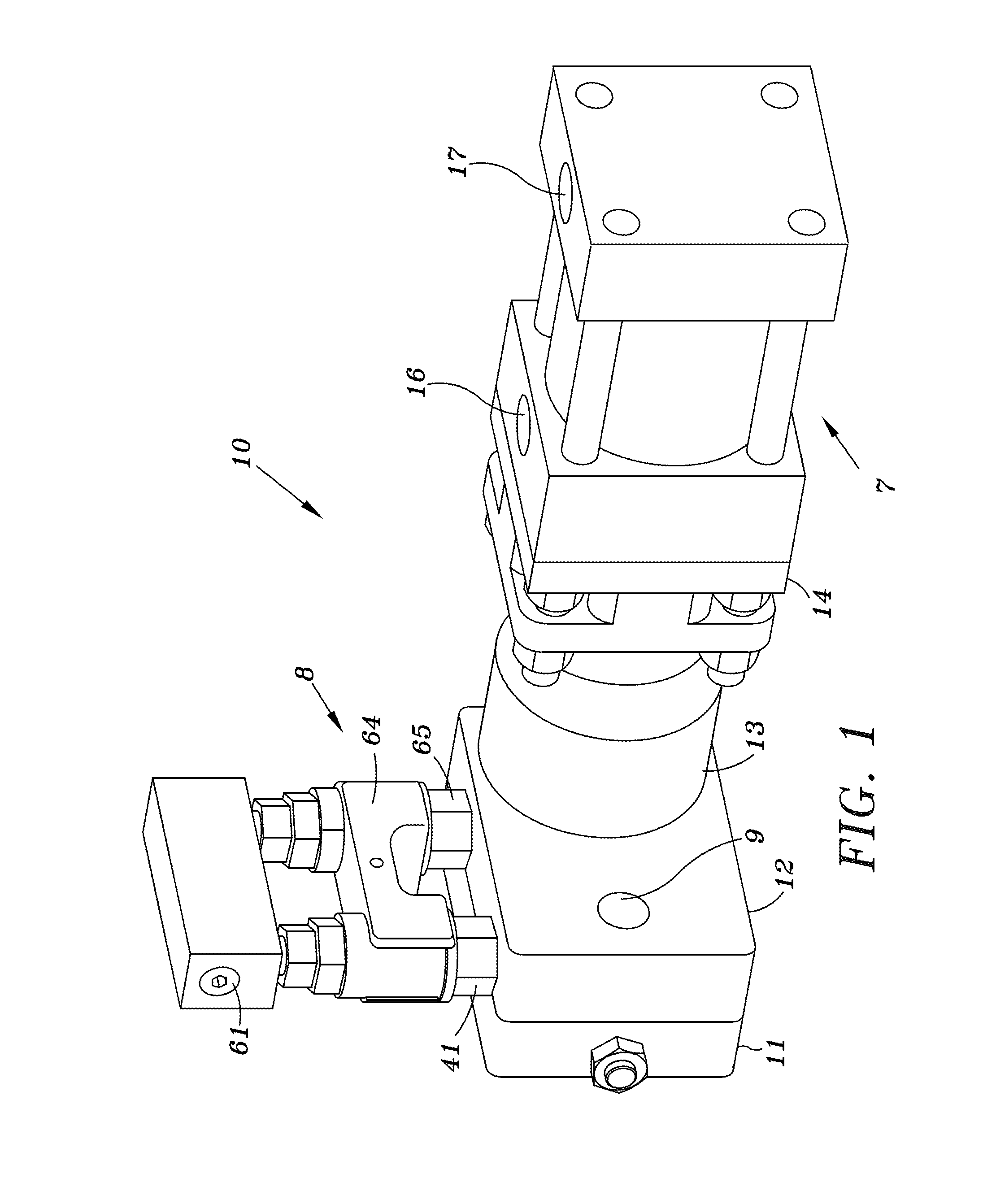
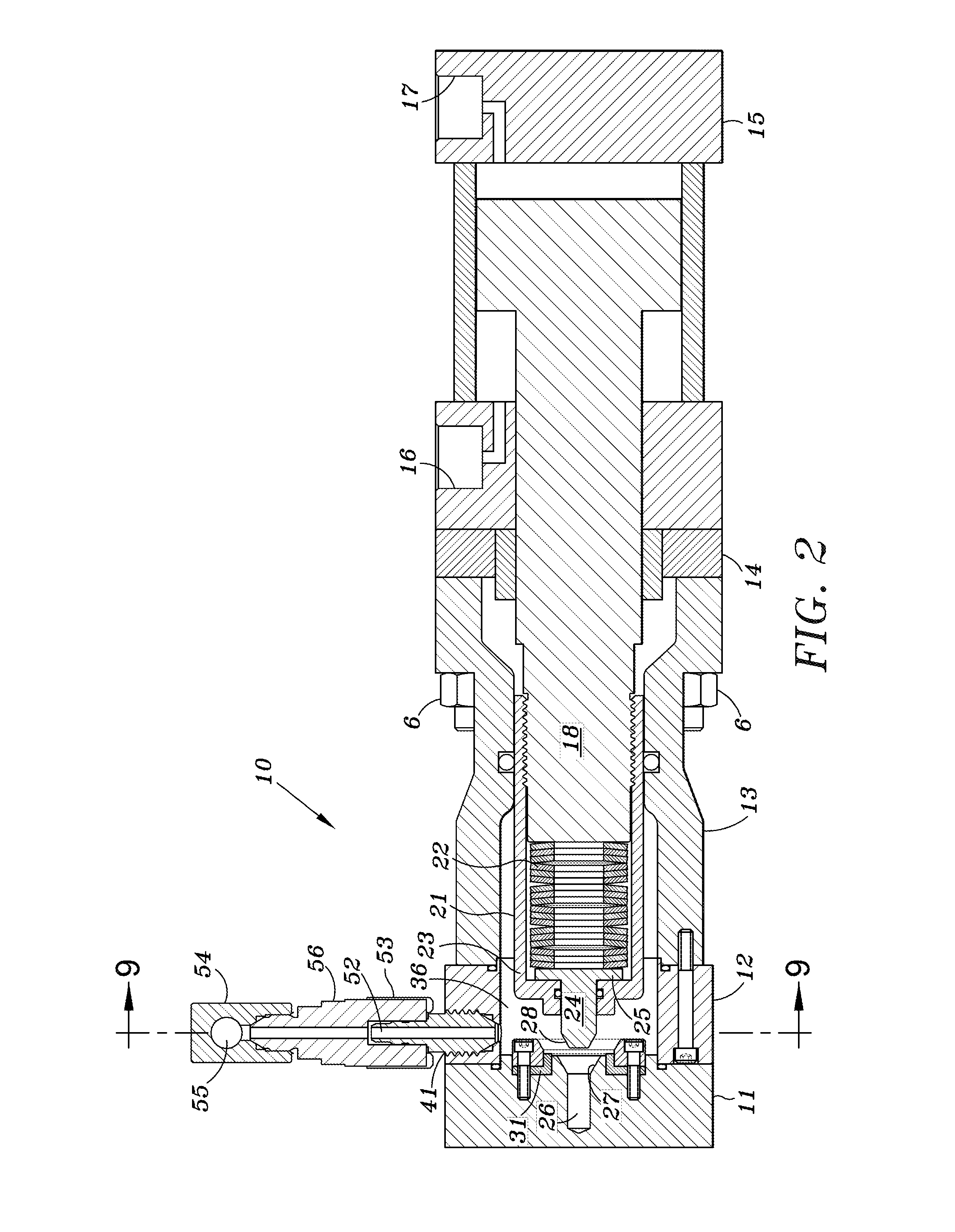
[0018]As shown in perception in FIG. 1, an embodiment of the invention of this application includes front housing members 11, 12 a central housing member 13, and a hydraulic actuating assembly 7 which includes fluid inlets and outlets 16, 17 for moving a piston 18 housed within the actuating assembly 7 as shown in FIG. 2.

[0019]A quick disconnect rupture disc assembly 8 is removable attached to the front portion of the valve and will be discussed in greater detail below.

[0020]Housing portions 11, 12, and 13 are bolted together as shown in FIG. 4 by a plurality of bolts 40 and 72.

[0021]Actuating assembly 7 and a spacer plate 14 are secured to housing 13 via a plurality of bolts 6.

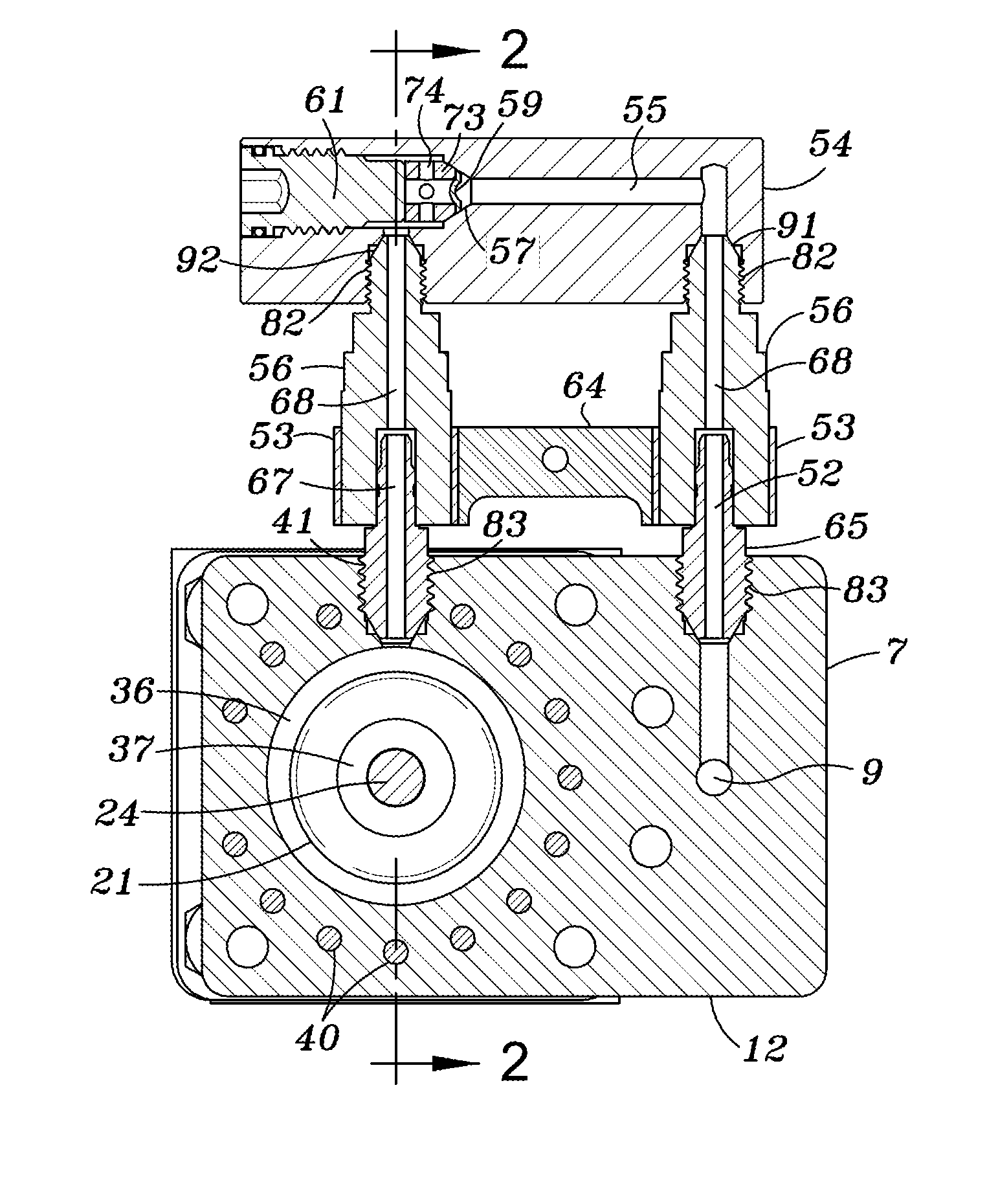
[0022]The interior of housing portion 11 is provided with a blind bore 26 which includes a first valve seat 27. An annular ring member 31 surrounds valve seat 27 and includes a second valve seat 32 as shown in FIG. 4. Ring member 31 is secured to housing portion 11 by a retainer ring 33 having a beveled secti...


PUM


Abstract

A dual seat valve assembly includes a first valve and a concentric second valve which together form a tight seal valve assembly. The valves open and close sequentially. A quick disconnect rupture disc assembly may be used in conjunction with the valve assembly to provide a required safety feature for testing high pressure fluid ruptures that include a dump valve.

Description

BACKGROUND OF THE INVENTION[0001]1. Field of the Invention[0002]The invention relates to a valve for regulating the flow of fluid. The valve may be used as a dump valve in a high pressure fluid system to relieve pressure when desired. It can also be used in any fluid system to provide an extremely tight seal with virtually no leakage, a condition sometimes referred to as a “bubble tight seal.”[0003]2. Background of the Invention[0004]A bubble tight seal is very desirable, and in some cases required, for pressure decay testing. Currently available technology utilizes highly polished metal to metal seat assemblies, or grease injectable sealing features. Valves using highly polished seat assemblies, can be made to have very small leaks, but not “bubble tight.” Additionally these valves are very susceptible to damage of their highly polished seat assemblies. Another current technology utilizes precision seat assemblies, not highly polished, and a special grease that seals the imperfecti...

Claims


Application Information

Patent Timeline
IPC IPC(8): F16K1/44F16K17/16F16K31/122
CPCF16K1/443F16K17/16F16K31/122
Inventor HILPERT, CLIFFORD L.HILPERT, JEFFERY
Owner ENGIP LLC
Why Eureka
Try Eureka