Channel coding rate matching method and device in communication system
A channel coding and rate matching technology, which is applied in the field of channel coding rate matching, can solve problems such as different locations, link performance degradation, and increased system implementation complexity, achieving the effect of enhancing transmission performance and reducing complexity
- Summary
- Abstract
- Description
- Claims
- Application Information
AI Technical Summary
Problems solved by technology
Method used
Image

Examples
Example Embodiment
[0118] Example one
[0119] As mentioned earlier, the starting position of the sub-packet is equal to an integer multiple of a certain value A.
[0120] Now A is the current modulation order N mod (That is, the starting position of the sub-package is N mod An integer multiple of) is taken as an example to illustrate in detail the process of using a method for selecting the start position of a sub-packet to avoid the possible misalignment of modulation symbols when two transmission sub-packets overlap.
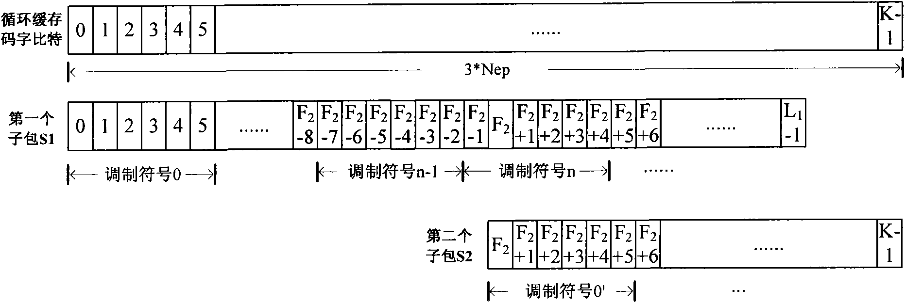
[0121] The information bit sequence is encoded and interleaved to obtain the mother code word. Put the mother code code word into length N FB_Buffer The circular buffer in which the data in the circular buffer includes a systematic bit part and a parity bit part. Then, according to the starting position of the HARQ sub-packet in the circular buffer and the length of the HARQ sub-packet, bits are selected from the circular buffer to generate the currently transmitted HARQ sub-packe...
Example Embodiment
[0136] Example two
[0137] As mentioned earlier, the starting position of the sub-packet is equal to an integer multiple of a certain value A.
[0138] Now take A as the least common multiple of multiple different modulation orders of 12 (that is, the starting position of the sub-packet is an integer multiple of the least common multiple of multiple different modulation orders of 2, 4, and 6) as an example to illustrate the use of A method for selecting the start position of sub-packets to avoid the process of unaligned modulation symbols that may occur when two transmission sub-packets overlap.
[0139] The information bit sequence is encoded and interleaved to obtain the mother code word. Put the mother code code word into length N FB_Buffer The circular buffer in which the data in the circular buffer includes a systematic bit part and a parity bit part. Then, according to the starting position of the HARQ sub-packet in the circular buffer and the length of the HARQ sub-packet,...
Example Embodiment
[0153] Example three
[0154] As mentioned earlier, the starting position of the sub-packet is equal to an integer multiple of a certain value A.
[0155] Now A is the least common multiple of multiple modulation orders and the number of bits contained in a byte 24 (that is, the starting position of the sub-packet is multiple modulation orders 2, 4, 6, and the number of bits contained in a byte 8 An integer multiple of the least common multiple of) is taken as an example to illustrate in detail the process of using a method for selecting the start position of a sub-packet to avoid the possible misalignment of modulation symbols when two transmission sub-packets overlap.
[0156] The information bit sequence is encoded and interleaved to obtain the mother code word. Put the mother code code word into length N FB_Buffer The circular buffer in which the data in the circular buffer includes a systematic bit part and a parity bit part. Then, according to the starting position of the HA...
PUM
 Abstract
Description
Claims
Application Information
 - R&D Engineer
- R&D Manager
- IP Professional
- Industry Leading Data Capabilities
- Powerful AI technology
- Patent DNA Extraction
Browse by: Latest US Patents, China's latest patents, Technical Efficacy Thesaurus, Application Domain, Technology Topic.
© 2024 PatSnap. All rights reserved.Legal|Privacy policy|Modern Slavery Act Transparency Statement|Sitemap