Aircraft broadband wireless system and methods

a wireless system and broadband technology, applied in the field of communication systems, can solve the problems of more expensive gs antenna subsystems, and achieve the effects of higher link margins, higher data rates, and greater transmit power

Inactive Publication Date: 2009-07-23
THE BROWN FAMILY TRUST
View PDF0 Cites 75 Cited by
  • Summary
  • Abstract
  • Description
  • Claims
  • Application Information

AI Technical Summary

Benefits of technology

[0015]The present invention is directed to improvements in ground-to-aircraft and aircraft-to-ground broadband communications and more particularly to techniques for using very narrow-beam transmission (above 10 GHz), adaptive antennas such as variable beamwidth non-tracking or fixed beamwidth tracking antennas, adaptive modulation including varying numbers of individual channels or OFDM carriers and coding levels according to link capability and / or user demand, and GPS location information-based tracking and handoff. Cognitive radio technology can also be used by aircraft and GS transceivers to select a portion of the band that is not currently being used within a geographic area. Radios, while not transmitting, can sample the entire band and measure the noise power in each segment. The best segment choices could be shared between the aircraft and GS transceivers using the beacon transceiver. This technique could also be used to allow a greater transmit power to be used. This increased power would not cause interference into other users if there were no other users in the area. This increase in power would allow for the support of longer ranges, higher link margins (during rain fades) or higher data rates. The transmit power would be decreased back to some lower level whenever another user on the same frequency was detected. Alternatively, a new frequency segment may be identified where no other users are present and the higher transmit power resumed.

Problems solved by technology

Networks built from this type of GS will require fewer, but more expensive GS antenna subsystems.

Method used


Image

  • Aircraft broadband wireless system and methods
  • Aircraft broadband wireless system and methods
  • Aircraft broadband wireless system and methods

Examples


Embodiment Construction

[0040]The present invention will now be described more fully hereinafter with reference to the accompanying drawings, in which preferred embodiments of the invention are shown. This invention may, however, be embodied in many different forms and should not be construed as limited to the embodiments set forth herein. Rather, these embodiments are provided so that this disclosure will be thorough and complete, and will fully convey the scope of the invention to those skilled in the art. Like numbers refer to like elements throughout, and prime and multiple prime notations, when used, refer to similar elements in alternate embodiments.

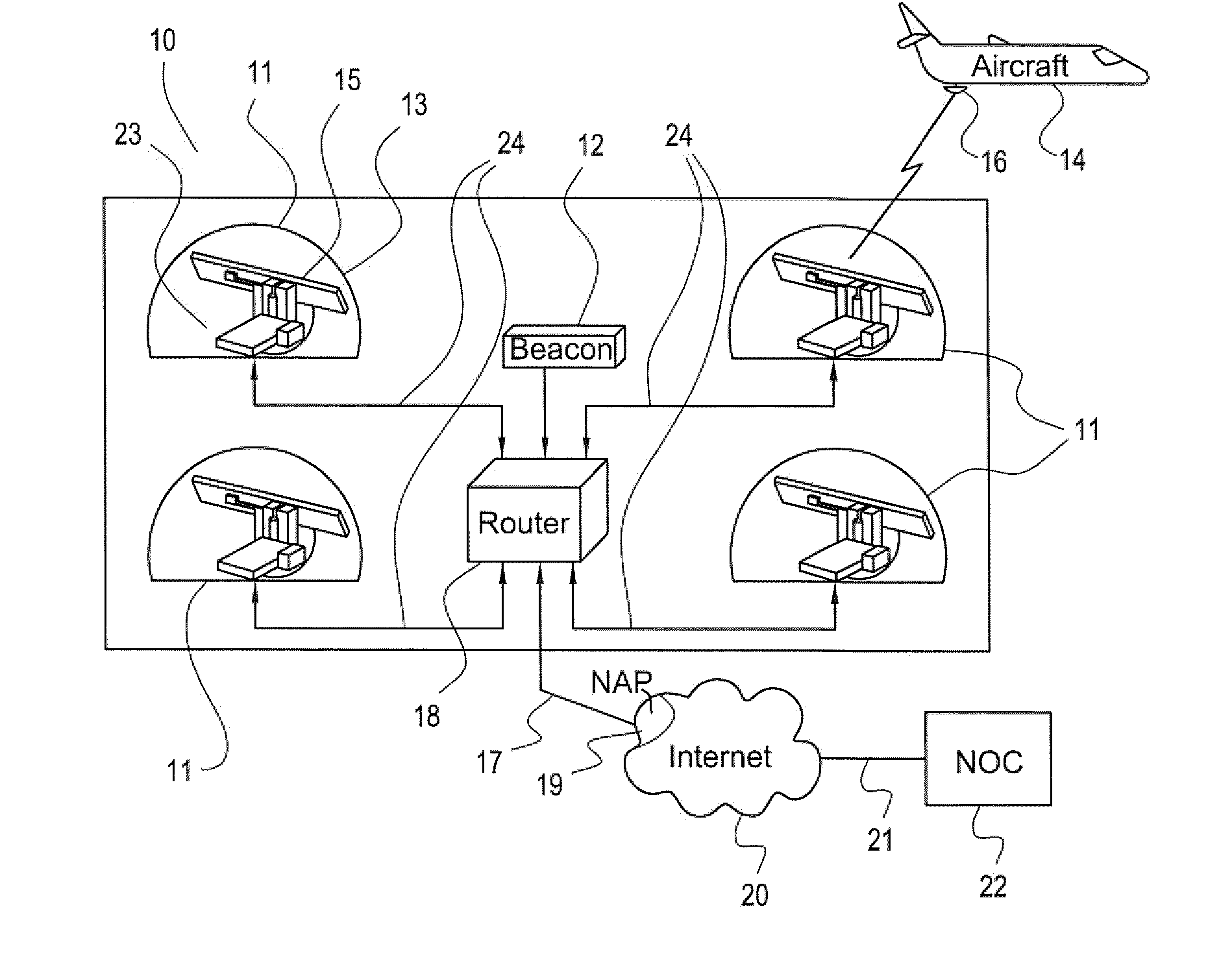
[0041]FIG. 1 illustrates the network architecture in accordance with one aspect of the invention. As shown in FIG. 1, there is a ground station (GS), generally indicated by 10. GS 10 is comprised of four (typical, certain GSs may have greater and some fewer) transceivers 11, in this non-limiting example, a beacon transceiver 12 and a router 18. Connected ...


PUM


Abstract

A broadband wireless system includes a plurality of spaced-apart ground stations for transmitting and receiving signals to and from a respective plurality of aircraft. Each of the plurality of ground stations may include a ground station transceiver including a ground station antenna carried by a mechanically steered platform, a ground station router in communication with the ground station transceiver, and a ground station beacon transceiver in communication with the ground station router. An aircraft transceiver may be carried by each of the plurality of aircraft to be positioned in communication with one of the plurality of ground stations. The aircraft transceiver may include an aircraft antenna mounted to the aircraft, an aircraft transceiver carried by the aircraft and in communication with the aircraft antenna, and an aircraft radio transceiver carried by the aircraft and in communication with the aircraft beacon transceiver. The broadband wireless system may also include a network operations center in communication with each of the ground stations via a global communications network. A ground station transceiver may transmit signals to and receives signals from not more than one aircraft at a time and ground station antenna may track the aircraft with which it is in communication.

Description

RELATED APPLICATIONS[0001]This application claims the benefit of U.S. Provisional Patent Application Ser. No. 61 / 014,539 titled Techniques for Broadband Communications for Aircraft filed on Dec. 18, 2007, the entire contents of which are incorporated herein by reference.FIELD OF THE INVENTION[0002]The present invention relates to communications systems and, more specifically, to communications systems for providing broadband data access aboard aircraft.BACKGROUND OF THE INVENTION[0003]Various techniques have been proposed to provide broadband communications to aircraft for the purpose of, for example, Internet or messaging service to passengers and / or crew. These methods are typically expensive in terms of cost-per-megabit / second of service. Further, these methods may provide insufficient bandwidth to be considered “broadband” for a large or mid-sized passenger aircraft. The methods may also lack scalability needed for Continental US (CONUS) or European coverage, for example.[0004]O...

Claims


Application Information

Patent Timeline
Patent Type & Authority Applications(United States)
IPC IPC(8): H04W4/00H04W84/02
CPCH04B7/18506H04W84/06H04W84/005H01Q3/24H01Q3/242
Inventor STILES, W. HERSCHELWOLCOTT, THEODORE J.WALDMAN, DANA R.GERHARDT, EDWARD C.
Owner THE BROWN FAMILY TRUST
Why Eureka
Try Eureka