Electrical connector with enhanced jack interface

a technology of jack interface and electric connector, which is applied in the direction of coupling device connection, coupling contact member, two-part coupling device, etc., can solve the problems of signal degradation, inability to meet the needs of users, and inherent weaknesses of jacks such as the rj-45 that can be expected to become more serious, so as to improve transmission performance in differential pairs

Inactive Publication Date: 2007-03-27
COMMSCOPE TECH LLC
View PDF12 Cites 75 Cited by
  • Summary
  • Abstract
  • Description
  • Claims
  • Application Information

AI Technical Summary

Benefits of technology

[0009]In a further aspect, an electrical connector is provided that includes a housing holding a plurality of contacts, symmetrically arranged in differential pairs about a longitudinal axis. The housing has a mating end and a wire receiving end. An organizer is configured for attachment to the wire receiving end of the housing. The organizer defines a central opening that receives a plurality of signal wires carrying differential signals. The organizer arranges the wires in a pattern to enhance transmission performance in the differential pairs.

Problems solved by technology

One source of signal degradation is crosstalk between multiple signal paths.
The RJ-45 plug design is dictated by industry standards and is inherently susceptible to crosstalk.
The shortcomings that are inherent in jacks such as the RJ-45 can be expected to become more serious as system demands continue to increase.
Another source of signal degradation is return loss resulting from signal reflections along the conductors.
Improving return loss performance has proven to be difficult.

Method used


Image

  • Electrical connector with enhanced jack interface
  • Electrical connector with enhanced jack interface
  • Electrical connector with enhanced jack interface

Examples


Embodiment Construction

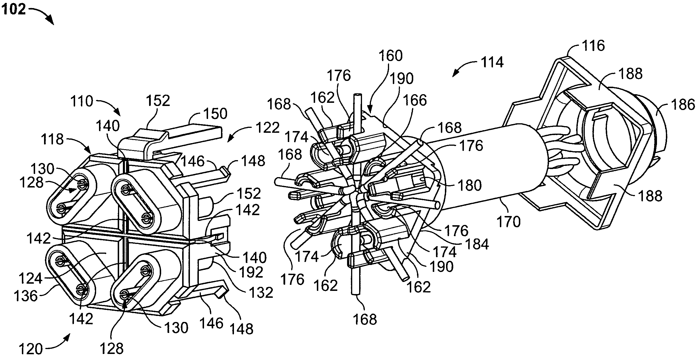
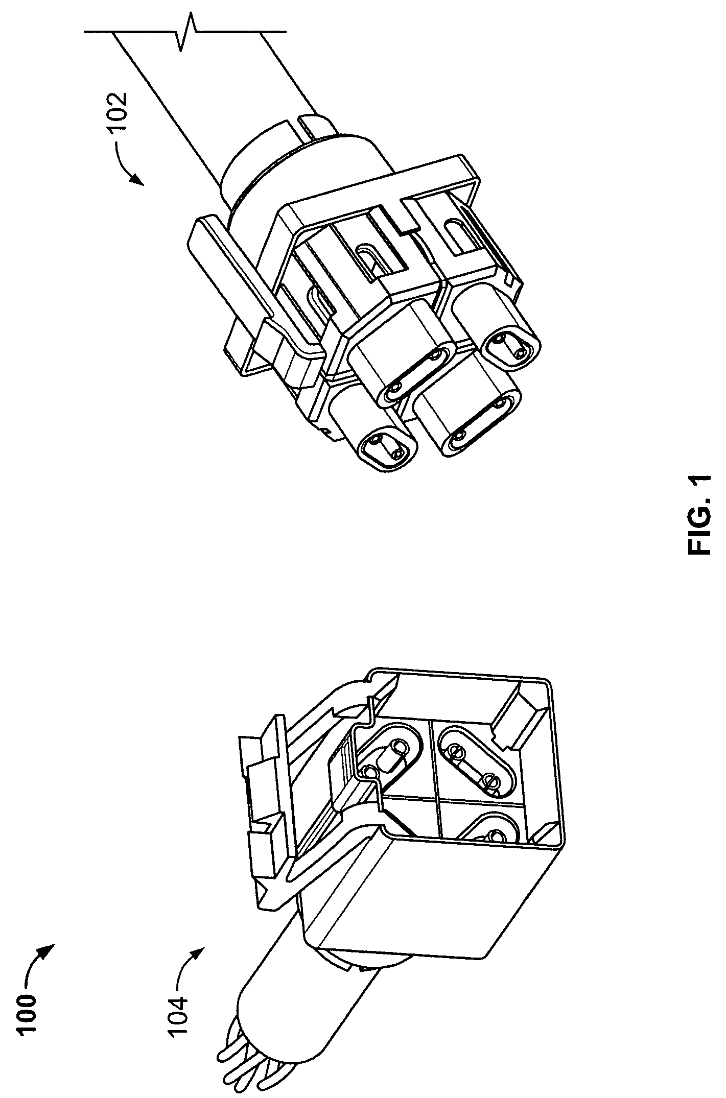
[0022]FIG. 1 is a perspective view of a connector assembly 100 formed in accordance with an exemplary embodiment of the present invention. The assembly includes a plug 102 and a jack 104 that are configured to mate with one another. The jack 104 may be mounted on a wall or panel, or, alternatively, may be mounted in an electrical device or apparatus having a communications port through which the device may communicate with other external networked devices. The assembly 100 will be described in terms of an assembly carrying four differential signal pairs. However, it is to be understood that the benefits described herein are also applicable to other connectors carrying fewer or greater numbers of signal pairs in alternative embodiments. The following description is therefore provided for illustrative purposes only and is but one potential application of the inventive concepts herein.

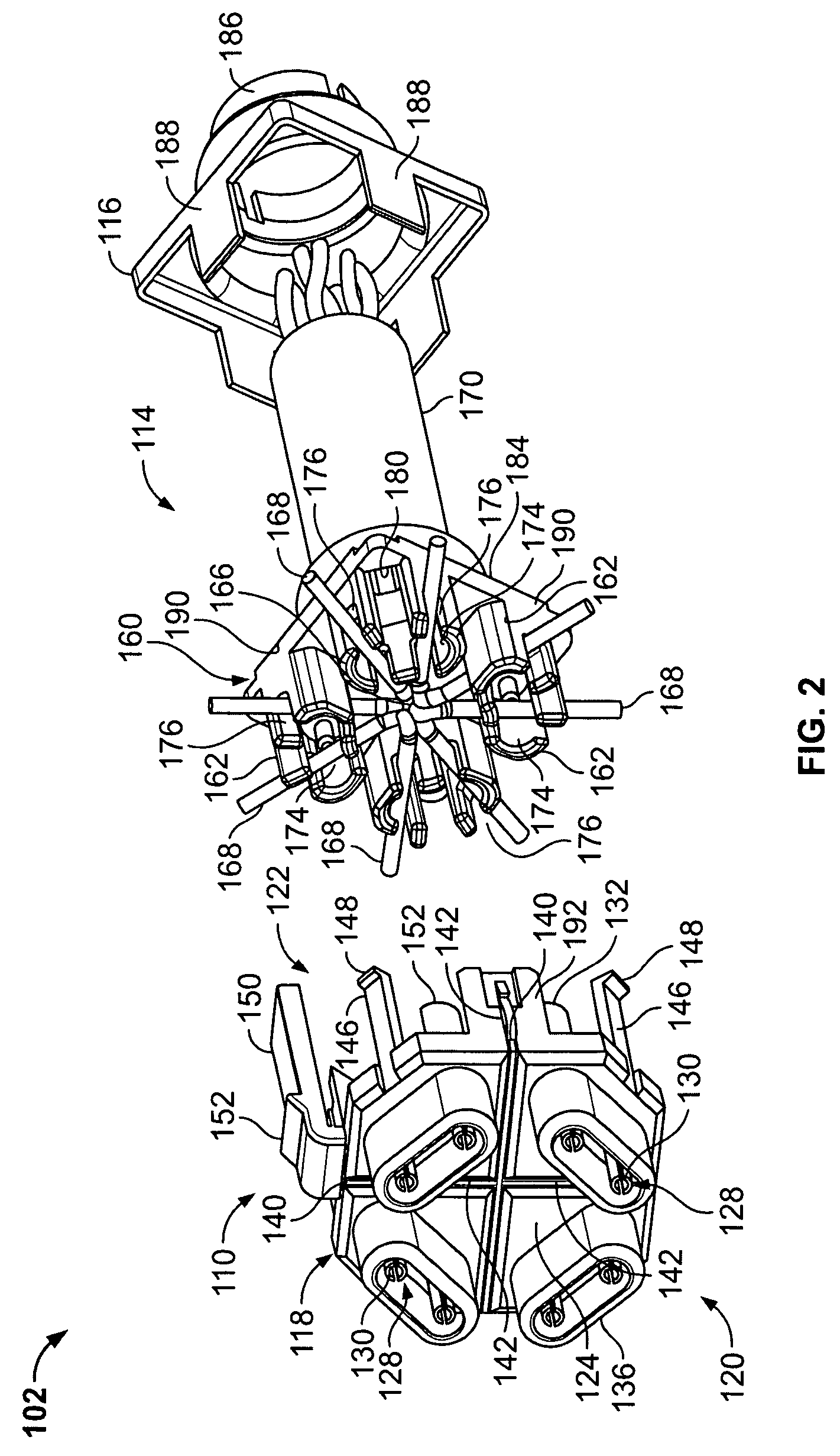
[0023]FIG. 2 illustrates an exploded view of the plug 102. The plug 102 includes a housing 110, an org...


PUM


Abstract

A connector includes a housing having a mating end, a wire receiving end, and a longitudinal axis therethrough. The housing holds a plurality of contacts grouped in differential pairs and arranged about the axis. At least one shielding member is located within the housing. The shielding member isolates each differential contact pair from an adjacent differential contact pair. An organizer is configured for attachment to the wire receiving end of the housing. The organizer defines a central opening that receives a plurality of signal wires carrying differential signals. The organizer includes a plurality of wire guides arranged about and extending radially outward from the central opening. The wire guides receive the signal wires.

Description

BACKGROUND OF THE INVENTION[0001]The invention relates generally to electrical connectors, and more particularly, to a connector that minimizes crosstalk among signal conductors in the connector, minimizes return loss in a pair of signal conductors in the connector, and minimizes alien cross talk from signal conductors in neighboring connectors.[0002]In electrical systems, there is increasing concern for preserving signal integrity as signal speed and bandwidth increase. One source of signal degradation is crosstalk between multiple signal paths. In the case of an electrical connector carrying multiple signals, crosstalk occurs when signals conducted over a first signal path are partly transferred by inductive or capacitive coupling into a second signal path. The transferred signals produce crosstalk in the second path that degrades the signal routed over the second path.[0003]For example, a typical industry standard type RJ-45 communication connector includes four pairs of conducto...

Claims


Application Information

Patent Timeline
Patent Type & Authority Patents(United States)
IPC IPC(8): H01R13/648
CPCH01R4/2441H01R13/6272H01R13/6592H01R31/06H01R13/6589H01R13/65807H01R4/2433H01R24/64
Inventor BERT, LINDA ELLENDENOVICH, SAMEBERLE, JR., JAMES JOSEPHMARTIN, RALPH SYKESGREEN, MICHAEL PATRICK
Owner COMMSCOPE TECH LLC
Why Eureka
Try Eureka