Steerable device for introducing diagnostic and therapeutic apparatus into the body

a technology of diagnostic and therapeutic equipment and steerable devices, which is applied in the field of steerable devices, can solve the problems of reducing the thickness of the wall, affecting the stability of the body, so as to achieve the effect of sacrificing the steering ability and thinning the wall

Inactive Publication Date: 2011-07-05
BOSTON SCI SCIMED INC
View PDF88 Cites 79 Cited by
  • Summary
  • Abstract
  • Description
  • Claims
  • Application Information

AI Technical Summary

Benefits of technology

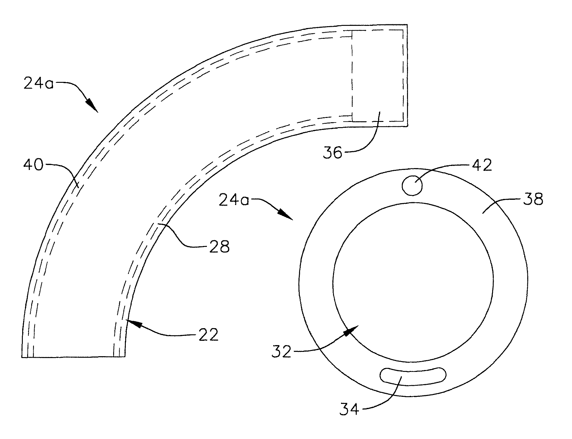
[0012]Accordingly, the general object of the present inventions is to provide apparatus that avoids, for practical purposes, the aforementioned problems. In particular, one object of the present inventions is to provide a steerable apparatus for introducing diagnostic and therapeutic apparatus into the body, such as a steerable sheath, having a thinner wall than conventional apparatus without sacrificing steerability.
[0014]The present apparatus provides a number of advantages over conventional steerable apparatus for introducing diagnostic and therapeutic apparatus into the body. For example, the non-circular steering wire distal portion distributes the forces generated during deflection over a greater surface area than a steering wire having a circular cross-section. The redistribution of forces over a greater area reduces the amount strength required to prevent the steering wire from tearing through the distal portion of the tubular members, sheaths or other elongate bodies during deflection. As a result, the present elongate body may be made thinner than the tubular members, sheaths or other elongate bodies in conventional steerable apparatus formed from the same material.
[0015]Use of the present non-circular steering wire also prevents out of plane bending. The non-circular portion of the steering wire also provides a larger surface area for attaching the steering wire to the distal portion of the elongate body or an element within the elongate body, thereby making manufacturing easier and, due to the larger bonding area, decreasing the likelihood that the steering wire and elongate body will become disconnected.
[0016]In order to accomplish some of these and other objectives, an apparatus in accordance with one embodiment of a present invention includes an elongate body having a lumen extending therethrough, a steering wire associated with the distal portion of the elongate body, and a stiffening member associated with the distal portion of the elongate body. The present apparatus provides a number of advantages over conventional steerable apparatus for introducing diagnostic and therapeutic apparatus into the body. For example, the stiffening member will prevent buckling of the elongate body distal portion during bending. The stiffening member may also be configured such that it will return the elongate body distal portion to a neutral position after a steering operation, influence the curvature of the elongate body during steering, provide a pre-bend in a direction other than the direction in which the distal portion is bent during steering, and increase the torque transmission properties of the distal portion.
[0017]In order to accomplish some of these and other objectives, an apparatus in accordance with one embodiment of a present invention includes an elongate body proximal portion, an elongate body distal portion, and a steering wire having a distal portion operably connected to the elongate body distal portion. The elongate body distal portion is formed from distal members with different stiffnesses. Such apparatus provides a number of advantages over conventional steerable apparatus for introducing diagnostic and therapeutic apparatus into the body. For example, the stiffer distal member will prevent buckling of the elongate body distal portion during bending.

Problems solved by technology

This type of sheath lacks any onboard steering mechanism.
Rotation of the control knob causes one of the wires to impart a pulling force on the distal portion of the sheath, thereby causing the distal portion to deflect.
Heretofore, efforts to reduce wall thickness have been hampered by the fact that the wall strength of the tubular member distal portion must be sufficient to prevent the steering wire from tearing through the distal portion during deflection.
The inventors herein have determined that such solutions are less than optimal because they limit the flexibility and, therefore, the steerability of the distal portion of the sheath or other tubular member.
Moreover, it can be difficult to produce a distal portion that will bend to a specific radius of curvature using conventional structures and manufacturing techniques.

Method used


Image

  • Steerable device for introducing diagnostic and therapeutic apparatus into the body
  • Steerable device for introducing diagnostic and therapeutic apparatus into the body
  • Steerable device for introducing diagnostic and therapeutic apparatus into the body

Examples


Embodiment Construction

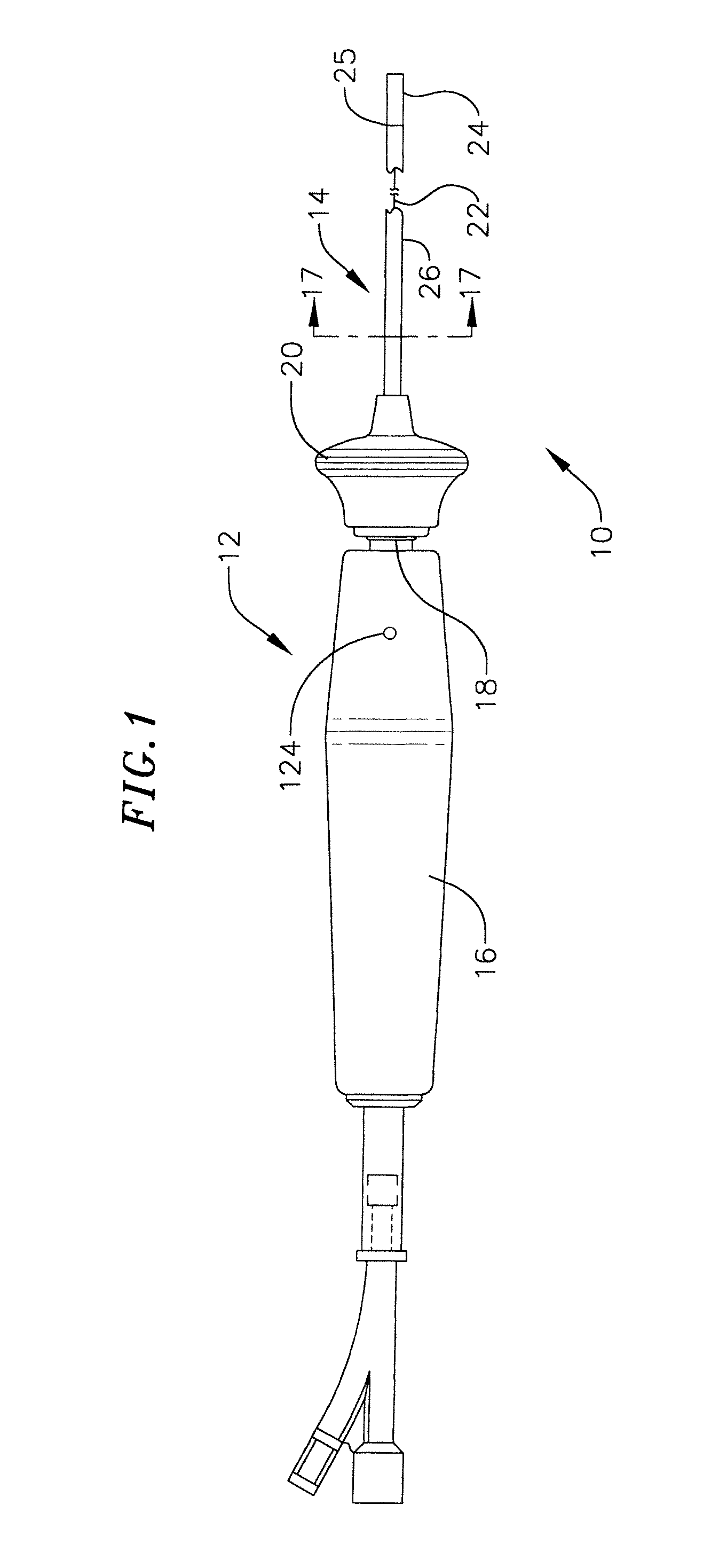
[0050]The following is a detailed description of the best presently known modes of carrying out the inventions. This description is not to be taken in a limiting sense, but is made merely for the purpose of illustrating the general principles of the inventions.

[0051]The detailed description of the preferred embodiments is organized as follows:

[0052]I. Overview

[0053]II. Elongate Body Distal Portion

[0054]III. Elongate Body Proximal Portion

[0055]IV. Handle

The section titles and overall organization of the present detailed description are for the purpose of convenience only and are not intended to limit the present inventions.

I. Overview

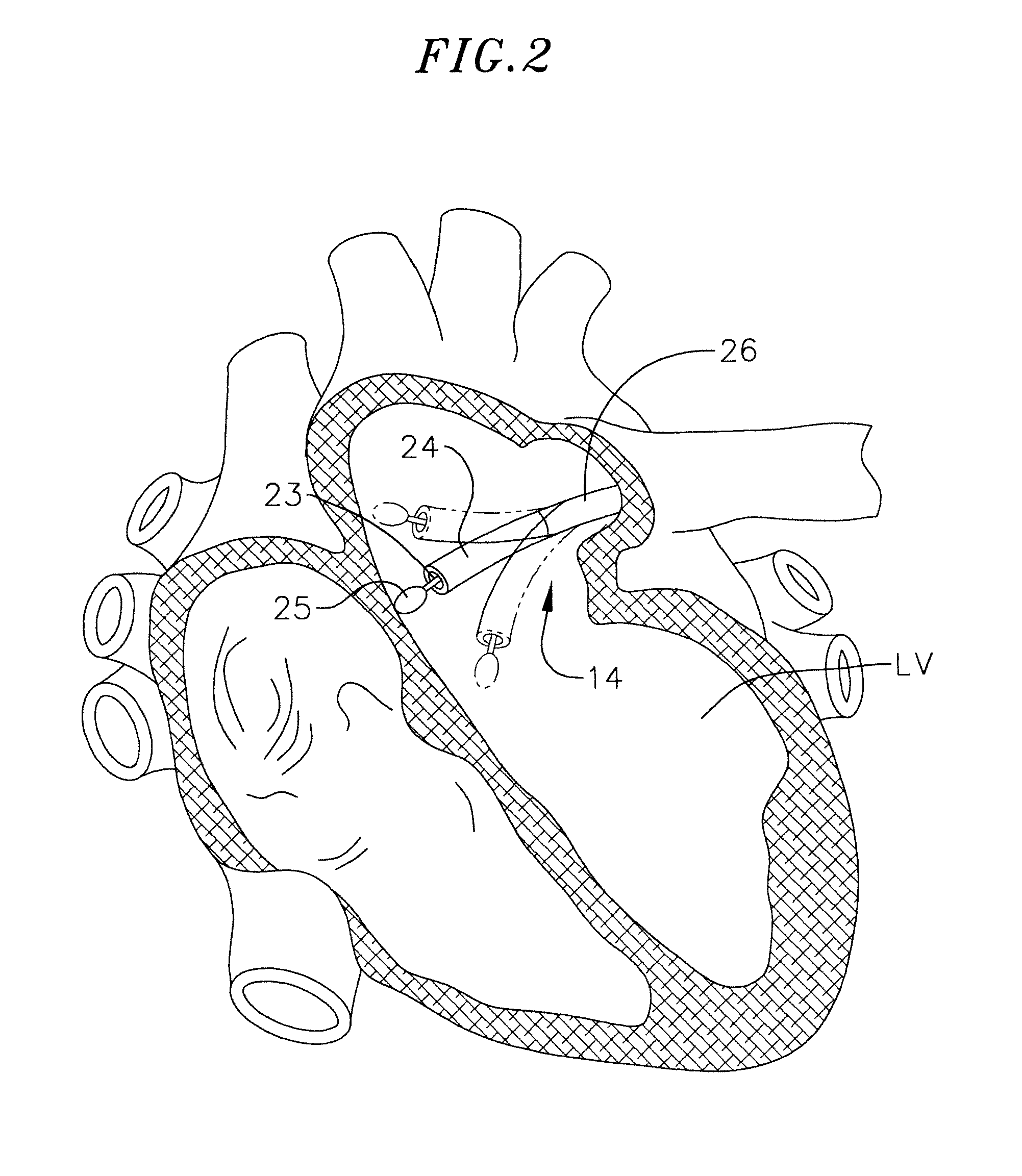
[0056]The present inventions may be used within body lumens, chambers or cavities for diagnostic or therapeutic purposes in those instance where access to interior bodily regions is obtained through, for example, the vascular system or alimentary canal and without complex invasive surgical procedures. For example, the inventions herein have application i...


PUM


Abstract

An apparatus including an elongate body having a lumen extending therethrough and a steering wire associated with the distal portion of the elongate body.

Description

CROSS-REFERENCE TO RELATED APPLICATIONS[0001]This application is a continuation-in-part of U.S. application Ser. No. 09 / 165,652, filed Oct. 2, 1998, now U.S. Pat. No. 6,544,215, which is incorporated herein by reference.BACKGROUND OF THE INVENTIONS[0002]1. Field of Inventions[0003]The present inventions relate generally to devices that are used to introduce diagnostic and therapeutic apparatus into the body.[0004]2. Description of the Related Art[0005]There are many instances where physicians must introduce diagnostic and therapeutic apparatus, such as diagnostic and therapeutic electrodes, ultrasound transducers, biopsy devices and other surgical tools, into the body. The diagnostic and therapeutic apparatus are often carried by catheters, which allow physicians to gain access to the body in a minimally invasive manner by way of bodily lumens. In cardiac treatment, for example, a catheter is advanced through a main vein or artery into the region of the heart that is to be treated.[...

Claims


Application Information

Patent Timeline
Patent Type & Authority Patents(United States)
IPC IPC(8): A61M25/00A61B17/00A61M25/01A61M25/16
CPCA61M25/0136A61M25/0138A61M25/0141A61M25/0144A61M25/0147A61B2017/00243A61M25/005A61M25/0051A61M2025/015
Inventor BENCINI, ROBERT F.THOMPSON, RUSSELL B.
Owner BOSTON SCI SCIMED INC
Why Eureka
Try Eureka