Hole cutter with minimum tooth pitch to blade body thickness ratio

a technology of blade body and blade, which is applied in the field of hole cutters, can solve the problems of not being configured to allow the chips or dust generated during cutting to flow through the aperture and away from the interior reducing so as to reduce the volume of chips and reduce the thickness of the blade body. , the effect of high tooth pitch

Active Publication Date: 2013-11-05
BLACK & DECKER INC
View PDF88 Cites 41 Cited by
  • Summary
  • Abstract
  • Description
  • Claims
  • Application Information

AI Technical Summary

Benefits of technology

[0012]In the currently preferred embodiments of the present invention, the means is defined by an axially-elongated aperture formed through the blade body. The aperture is axially spaced relative to the cutting edge, extends substantially in an axial direction of the blade body, and is configured to receive chips flowing from the cutting edge within the interior of the blade body and at least one of (i) into the aperture, and (ii) through the aperture, for preventing the collection of such chips within at least one of the interior of the blade body and an interface between the blade body and work piece. In some such embodiments, the axially-elongated aperture defines a first end adjacent to the cutting edge and axially spaced therefrom a first distance within the range of about 15 / 100 inch to about ⅜ inch, and a second end axially spaced further away from the cutting edge than the first end a second distance of at least about 1½ inches.
[0013]One advantage of the hole cutters of the present invention is that the substantially cylindrical blade body defines a relatively thin wall thickness within the range of about 0.032 inch to about 0.038 inch, and thus the hole cutters of the present invention can generate a significantly lesser volume of chips than prior art hole cutters of comparable diameters, tooth forms and pitch patterns. Yet another advantage of the hole cutters of the present invention is that they define a relatively high tooth pitch to blade body thickness ratio of at least about 110, preferably at least about 120, and most preferably within the range of about 130 to about 140. This unique combination of a relatively thin blade body, specified tooth pitch range, and relatively high tooth pitch to blade body thickness ratio, allows the hole cutters of the present invention to cut more efficiently, and to unexpectedly achieve significantly faster cutting speeds and blade life in comparison to prior art hole cutters. Further, despite the teaching in the prior art that a thicker wall thickness would be required, the hole cutters of the present invention are not only tough but achieve unexpectedly improved cutting performance.

Problems solved by technology

One of the drawbacks encountered with prior art hole cutters is that chips or dust, particularly when cutting wood, collects within the interiors of the hole cutters between the work piece slugs and the caps on the non-working ends of the hole cutters.
The apertures formed in the side walls of the blade bodies are designed to allow the insertion of screw drivers or like tools to remove work piece slugs, but are not configured to allow the chips or dust generated during cutting to flow through the apertures and away from the interiors of the blade bodies.
The collection of chips and dust within the interiors of the blade bodies and / or at the interfaces of the blade bodies and work pieces can significantly reduce the cutting efficiency and overall cutting speed and / or blade life of such hole cutters.
Another drawback encountered with prior art hole cutters is that the blade bodies are relatively thick, typically on the order of at least about 0.05 inch thick.
As a result, the cutting teeth are relatively wide, thus generating a substantial volume of chips and / or dust during cutting.
As a result, prior art hole cutters can become rapidly filled with chips and / or dust, and / or can rapidly collect chips and / or dust at the interfaces of the blade bodies and work pieces, giving rise to substantial heat during cutting that can soften or otherwise turn the paints or coatings on the hole cutters soft or gooey.
The soft or gooey paints or coatings, combined with the collected chips and dust, further degrade the cutting efficiency of the hole cutters and reduce overall cutting speed and / or blade life.

Method used


Image

  • Hole cutter with minimum tooth pitch to blade body thickness ratio
  • Hole cutter with minimum tooth pitch to blade body thickness ratio
  • Hole cutter with minimum tooth pitch to blade body thickness ratio

Examples


Embodiment Construction

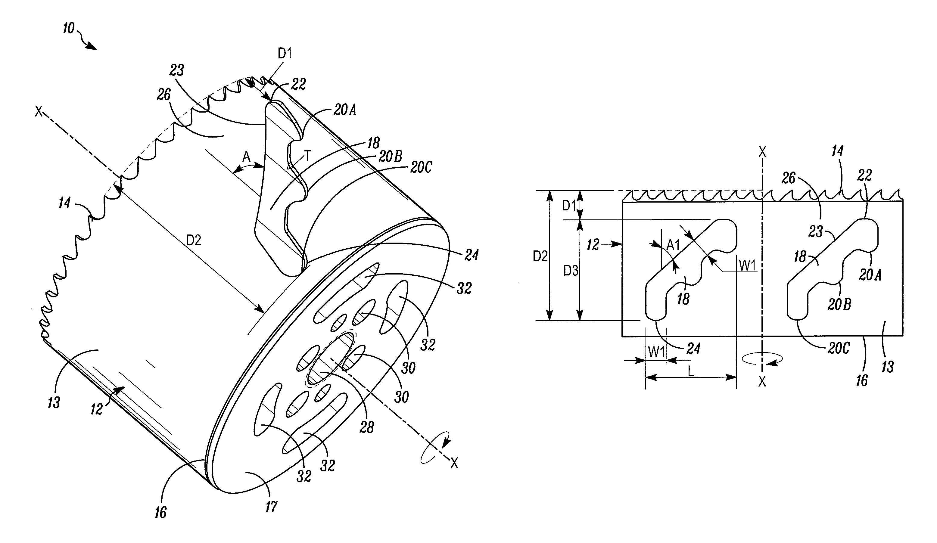
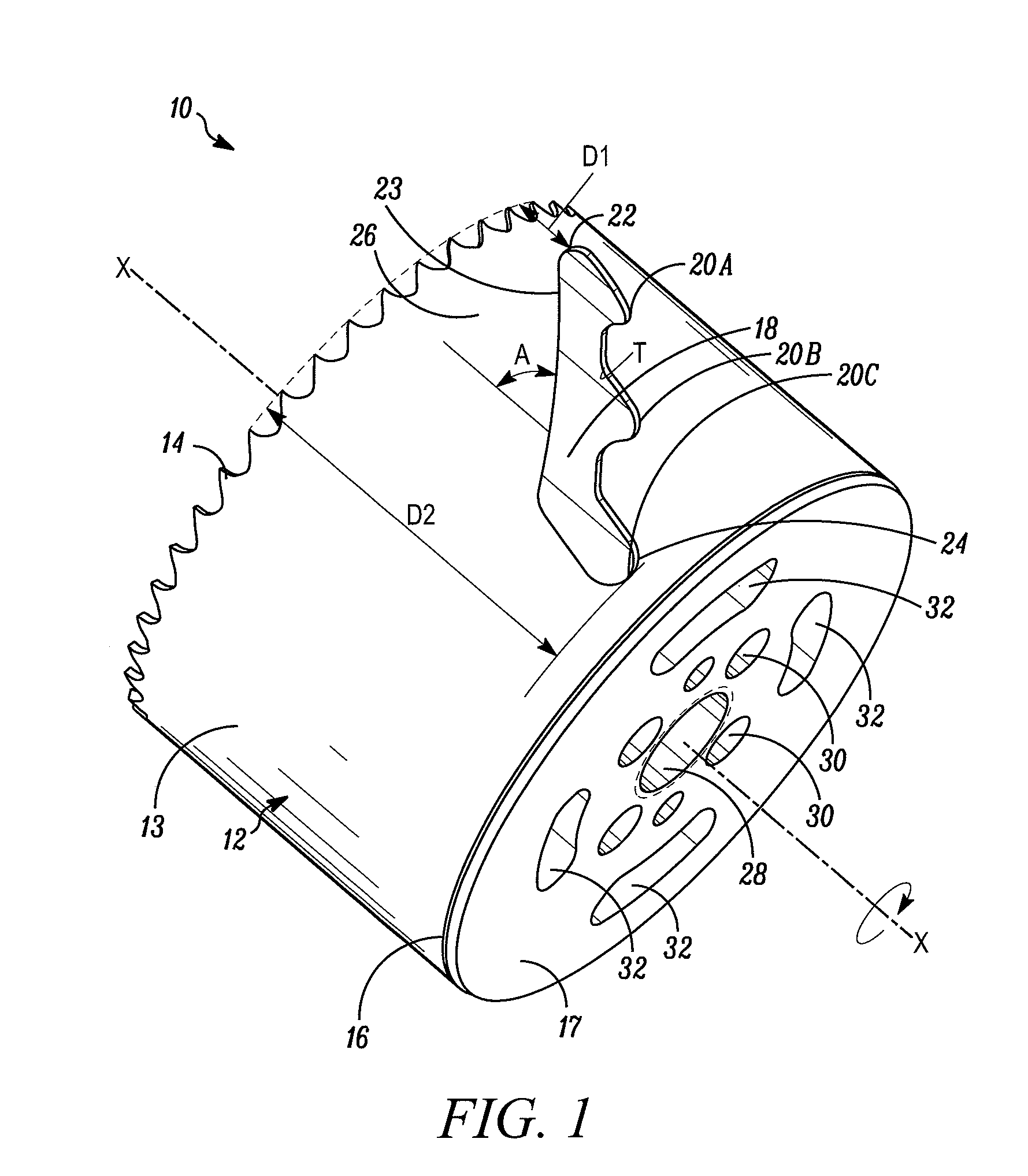
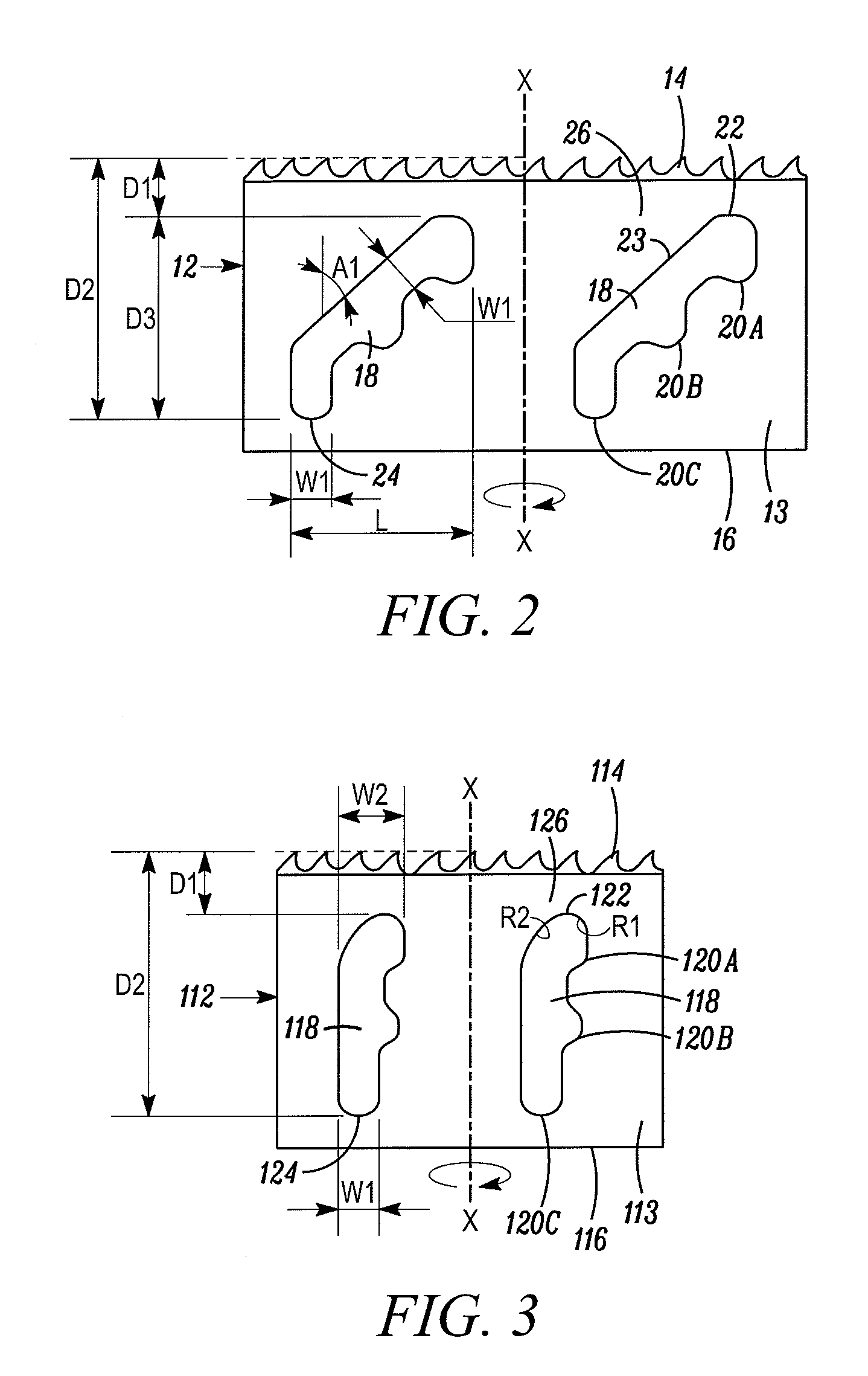
[0018]In FIG. 1, a hole cutter embodying the present invention is indicated generally by the reference numeral 10. The term “hole cutter” is used here to mean a tool that cuts holes in work pieces, such as wood or metal work pieces, and includes without limitation hole saws. The hole cutter 10 includes a blade body 12 defining a side wall 13. The blade body 12 is shown in FIG. 2 in its flattened state; however, as shown in FIG. 1, the blade body 12 is rolled or otherwise formed into a substantially cylindrical shape to form the hole cutter 10. As shown in FIG. 1, the side wall 13 extends around an axis of rotation “X” of the hole cutter 10 to define the substantially cylindrical blade body 12. One end of the blade body 12 is provided with a cutting edge 14 oriented substantially perpendicular to the axis of rotation X, and the opposing end of the blade body defines a rim 16. As shown in FIG. 1, a cap 17 is fixedly secured, such as by welding, to the rim 16 to enclose the respective ...


PUM

PropertyMeasurementUnit
thicknessaaaaaaaaaa
thicknessaaaaaaaaaa
widthaaaaaaaaaa

Abstract

A hole cutter for cutting a work piece, such as a wood and / or metal work piece, has a substantially cylindrical blade body defining a wall thickness within the range of about 0.032 inch to about 0.038 inch, and a cutting edge formed on one end of the blade body including a plurality of teeth defining an average tooth pitch within the range of about 3.5 TPI to about 5.5 TPI for cutting the work piece and forming chips therefrom. The substantially cylindrical blade body and cutting edge define an average tooth pitch to blade body thickness ratio of at least about 110.

Description

FIELD OF THE INVENTION[0001]The present invention relates to hole cutters, and more particularly, to hole cutters for cutting a variety of work pieces, such as wood and metal, and including features for increasing cutting speed and / or improving blade life.BACKGROUND INFORMATION[0002]A typical prior art hole cutter includes a cylindrical blade body defining a plurality of saw teeth on the cutting edge of the blade body, and one or more apertures formed through an intermediate portion of the blade body. Typically, smaller diameter hole cutters have fewer apertures formed through the blade bodies, and larger diameter hole cutters have more apertures formed through the blade bodies. The apertures formed through prior art hole cutter blade bodies may define a variety of different configurations to facilitate inserting a tool into the apertures, such as a screw driver, to remove circular work piece slugs from the interiors of the blade bodies.[0003]One of the drawbacks encountered with pr...

Claims


Application Information

Patent Timeline
Patent Type & Authority Patents(United States)
IPC IPC(8): B23B51/05B23B51/04
CPCB23B51/0406Y10T408/8957Y10T408/8953Y10T408/895B23B51/04B23B51/0467
Inventor KALOMERIS, CHARLES E.NOVAK, JOSEPH THOMASKORB, WILLIAM B.FITZGERALD, CHRISTOPHER F.
Owner BLACK & DECKER INC
Why Eureka
Try Eureka