

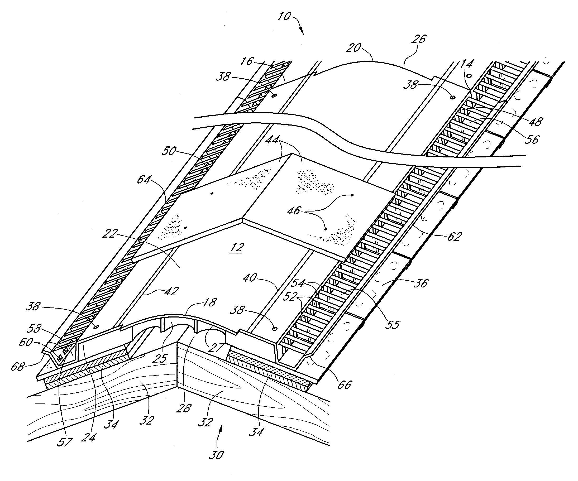
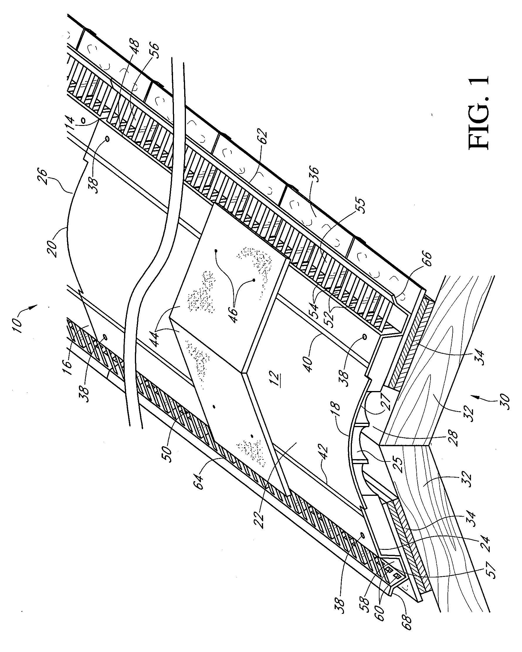
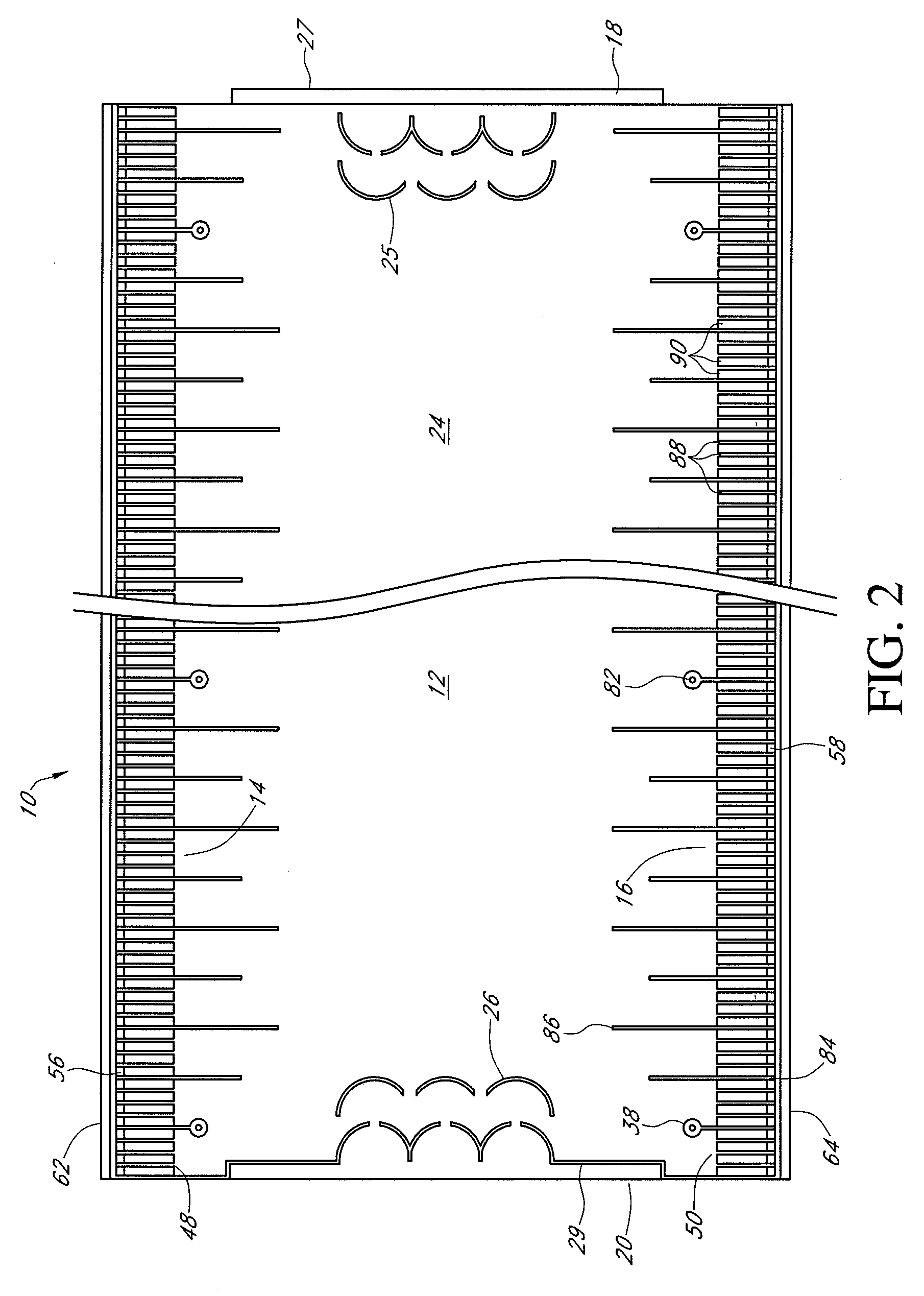
Roof ridge vent with improved trough
a technology of roof ridge vents and ridge vents, which is applied in ventilation systems, lighting and heating apparatus, heating types, etc., can solve the problems of inability to adapt easily, construction can be costly and laborious, and the vents are typically not durable, and do not allow adequate air flow
- Summary
- Abstract
- Description
- Claims
- Application Information
AI Technical Summary
Benefits of technology
Problems solved by technology
Method used
Image

Examples
Embodiment Construction
[0024]While modern ridge vent systems are an improvement over early ridge vents, there are still many shortcomings inherent in their designs. One problem of the prior art is that the drain trough region typically located between the sidewalls and wind baffles at the lateral edges of the ridge vent can accumulate leaves, twigs, gravel, airborne litter, and other natural and manmade debris. Although the placement of drain openings (also known as “weep holes”) at the trough or lower end of the wind baffles can effectively drain water and other small particles from the trough, the size of the weep holes is typically limited. Weep holes that are too large may undercut the very purpose of the baffles to prevent the entry of wind-driven rain and to provide wind resistance to create a low pressure zone in the troughs (which provides outward ventilation). Accordingly, the weep holes of modern ridge vents are typically too small to provide for the elimination of larger particles. Thus, the tr...
PUM
 Abstract
Description
Claims
Application Information