Catheterization assembly

a technology of catheter assembly and assembly plate, which is applied in the direction of suction device, intravenous device, wound drain, etc., can solve the problems of long-term use of indwelling catheter, lack of satisfactory catheterization kit, and individual need for intermittent catheterization, so as to and prevent the spillage of wetting liquid. high lubricating or slippery

Active Publication Date: 2012-05-15
COLORADO CATHETER
View PDF43 Cites 35 Cited by
  • Summary
  • Abstract
  • Description
  • Claims
  • Application Information

AI Technical Summary

Benefits of technology

[0014]The present invention provides a new catheter device or assembly that permits essentially sterile catheterization of the bladder and establishment of free drainage of urine from the discharge end of the catheter without using conventional sterile field technique. The new catheter assembly is an alternative to, or an improvement over, existing “unitized” self-lubricating catheterization assemblies. In accordance with certain exemplary embodiments of the present invention, a urinary catheterization device is provided that generally includes a (a) catheter introducer including a first guide section including an inlet for receiving a urinary catheter tip and a second guide section including an aperture for releasing the catheter tip, the aperture adapted for contacting a urethral opening; (b) a catheter including a tip having at least one urine inlet, a urine outlet, and an outer surface, at least a urethra-insertable portion of the outer surface being hydrophilic, the catheter tip being initially disposed in the first guide section; (c) a flexible walled sheath comprising first and second ends, a lumen, and a length that is less than that of the catheter, the sheath first end being sealingly attached to the catheter at a non-urethra-insertable location on the catheter adjacent to the outlet, and the sheath second end being sealingly attached to the first guide section, whereby the catheter tip is retained in the first guide section and prevented from slipping into the sheath lumen, the inlet and at least the urethra-insertable portion of the catheter being enclosed in the sheath lumen, the sheath adapted for containing a liquid for wetting the hydrophilic catheter or at least the urethra-insertable portion thereof; (d) a diaphragm disposed in the catheter introducer between the first and second guide sections, and adapted for being pierced by the catheter tip and for deterring or preventing leakage of the wetting liquid from the first guide section into the second guide section before and after being pierced by the catheter tip.
[0017]Advantageously, the urine outlet is separated from the sheath lumen so that the sheath lumen is not in fluid communication with the collection bag, and thus the wetting liquid is prevented from entering the urine collection bag. In certain embodiments, the sheath first end is sealingly attached to the catheter adjacent to the site of attachment of the urine collection bag, or adjacent thereto.
[0018]In certain embodiments, the sheath is of approximately equal length to that of the urethra-insertable catheter portion and the catheter tip is retained in the first guide section and is prevented from slipping into the sheath interior when the device is fully extended.
[0022]Further provided in accordance with certain embodiments of the present invention is a method of deterring or preventing spillage of a wetting liquid during catheterization of a urinary bladder. The method includes: (a) providing an above-described device including an attached urine collection vessel, or providing an above-described device without an attached urine collection vessel and providing for urine disposal or collection; (b) placing the catheter introducer outlet against the urethral opening of an individual in need of catheterization; (c) grasping the flexible walled sheath and wetted hydrophilic catheter together at one or more first position or series of positions along the urethra-insertable length of the catheter, and urging the catheter tip into the diaphragm such that the diaphragm is pierced and such that a portion of the sheath is caused to collapse toward the first guide section; (d) re-grasping the flexible walled sheath and wetted catheter together at one or more second position or series of positions along the urethra-insertable length of the catheter, and moving the catheter tip through the pierced diaphragm, whereby a further portion of the sheath is caused to collapse toward the first guide section and the pierced diaphragm or a portion thereof forms a leak resistant slidable seal around the moving catheter; (e) re-grasping the flexible walled sheath and wetted catheter together at one or more third position or series of positions along the urethra-insertable length of said catheter, and urging the catheter tip through said second guide section, through said outlet, into the urethra and into the urinary bladder, whereby a further portion of said sheath is caused to collapse toward said first guide and urine flows into said catheter tip and out said urine discharge outlet; (f) after emptying the bladder, removing the catheter from the bladder and urethra by substantially reversing each of steps (e)-(b). In certain embodiments, the method also includes (g) measuring the amount of urine collected in said container.
[0023]Still further provided in accordance with certain embodiments of the present invention is a method of deterring or preventing spillage of a wetting liquid during catheterization of a urinary bladder. This method includes: (a) providing an above-described catheterization device wherein the aperture of the catheter introducer, from which the catheter exits, initially has a removable seal, and the second guide section contains at least an amount of a wetting liquid sufficient to wet the hydrophilic outer surface of the catheter to render the catheter highly lubricated or slippery. The method further includes (b) providing for urine disposal or collection, if the device does not include an attached urine collection container. In accordance with this method, the flexible walled sheath and the catheter are grasped together at one or more first position or series of positions along the urethra-insertable length of the catheter, and by urging the catheter tip into the diaphragm, the diaphragm is pierced, and a portion of the sheath is caused to collapse or gather toward the first guide section. The method further includes (d) withdrawing the catheter tip from the pierced diaphragm leaving an opening between said first and second guide sections which allows said wetting liquid to enter said first guide section. If necessary, (e) at least a soft second guide section of the catheter introducer is squeezed or compressed with the fingers of the user, to facilitate movement of the wetting liquid through said diaphragm opening and into said first guide section and sheath interior. After the catheter inside the sheath and first guide section is wetted by the liquid, the procedure continues with removing the seal and placing said catheter introducer outlet against the urethral opening of an individual in need of catheterization. The seal or closure is sufficiently strong to resist leakage from aperture of the pressurized liquid when the second guide section is squeezed. The method further includes (g) returning said wetted catheter tip through said diaphragm opening forming a leakage resistant seal around the moving catheter; (h) regrasping said flexible walled sheath and wetted catheter together at one or more subsequent position or series of subsequent positions along the sheath-enclosed urethra-insertable length of said catheter, and urging the catheter tip through said second guide section, through said outlet, into the urethra and into the urinary bladder, whereby further portions of said sheath are caused to collapse toward said first guide, until urine flows into said catheter tip and out said urine discharge outlet; (i) after emptying the bladder, removing the catheter from the bladder and urethra by reversing step (h).
[0024]An above-described catheterization device according to the present invention is an economic and desirable alternative to conventional catheterization trays used by health care personnel. The present catheter device is simple to use for either assisted or self-catheterization, with the individual in either a supine or non-supine position. The hydrophilic catheterization device and its method of use provide a decreased risk of contamination and infection over other “unitized” assemblies, and provide for easy waste disposal or collection for measurement or analysis using a conventional container without skewing of such measurements due to pooling of the wetting liquid with the collected urine. This device and catheterization method is practical for use by health care providers in hospitals, mobile emergency facilities, doctors' offices, rehabilitation facilities, nursing homes and the like. It is also advantageous for performing temporary catheterizations by individuals, is easy to use for self-catheterization in the home or in a public restroom, and provides for a high degree of sanitation during handling and use. A catheterization kit according to the present invention also lends itself to being economically manufactured and sold for one-time-only use, which will be of great benefit in reducing the incidence of urethral and bladder infections in catheterization patients. These and other features and advantages will be apparent from the detailed description and drawings that follow.

Problems solved by technology

The need for intermittent catheterization of an individual sometimes arises due to problems typically associated with long term use of indwelling catheters, such as infections, urethral damage, and bladder damage.
Long term use of an indwelling catheter is also a risk factor for bladder cancer.
Some of the major difficulties that arise in self-catheterization are the lack of satisfactory catheterization kits, the problem of maintaining the required level of sanitation during the procedure, and the difficulty of sometimes performing the procedure under conditions of restricted space and privacy.
Maintaining a sterile field during the procedure can still be a problem, however, and the “cath tray” procedure is impractical for use with some individuals and situations today.
First, it is very difficult, if not impossible, for individuals who are performing self-catheterization to adhere strictly to sterile technique.
Secondly, these individuals are required to catheterize themselves between 3 and 6 times a day, and the cost of a new sterile catheter and the accessories required to perform sterile catheterization become excessively expensive for many users.
As a result, the use of non-sterile technique will many times result in contamination and subsequent infection of the urinary tract, causing significant morbidity and cost to the patient and society.
Even if cost considerations were not a major consideration for the user, with most conventional self-contained sterile units where the collection bag doubles as the catheter insertion cover, the catheter is extremely difficult for the user to grasp and insert.
This is particularly a problem for self-catheterization users who may also have neurological problems that limit manual dexterity.
Also, with some of the available catheter kits and methods, the catheter is either not sufficiently lubricated during insertion (and thus requires the additional application of possibly non-sterile lubricant), or the catheter is too slick with lubricant and cannot effectively be grasped through an insufficiently flexible bag.
As a practical matter, most individuals who would prefer to self-catheterize cannot conveniently do so, and maintain the required level of sanitation using many of the existing catheterization apparatus.
A significant difficulty with conventional catheterization assemblies that merely package the catheter inside a sterile urine collection bag is that the flexible bag is typically neither thin-walled and pliant enough to permit grasping and feeding the catheter into the urethra, nor is it sufficiently rigid for accurate urine output measurement or for specimen removal.
With some of the available catheter kits, there is also the further problem of a flexible or slippery catheter tending to drop down into the collection bag.
While the elimination of a dry catheter and lubricant may have some advantages, a serious drawback that is common to many hydrophilic catheter arrangements and catheterization methods is the tendency for the wetting liquid to flow out of the end of the catheter and onto the user or the user's bed or wheelchair as the catheter is drawn out of its packaging.
Another drawback is that some hydrophilic catheter kits do not prevent the slippery hydrophilic catheter from falling down into an attached urine collection bag.
If the catheter slips into the urine collection bag after removal from the urethra, it can skew the urine collection volume.
Still another problem with some conventional devices is that the wetting liquid can pool with the collected urine, skewing volume measurements and urinalysis results.

Method used


Image

  • Catheterization assembly
  • Catheterization assembly
  • Catheterization assembly

Examples


Embodiment Construction

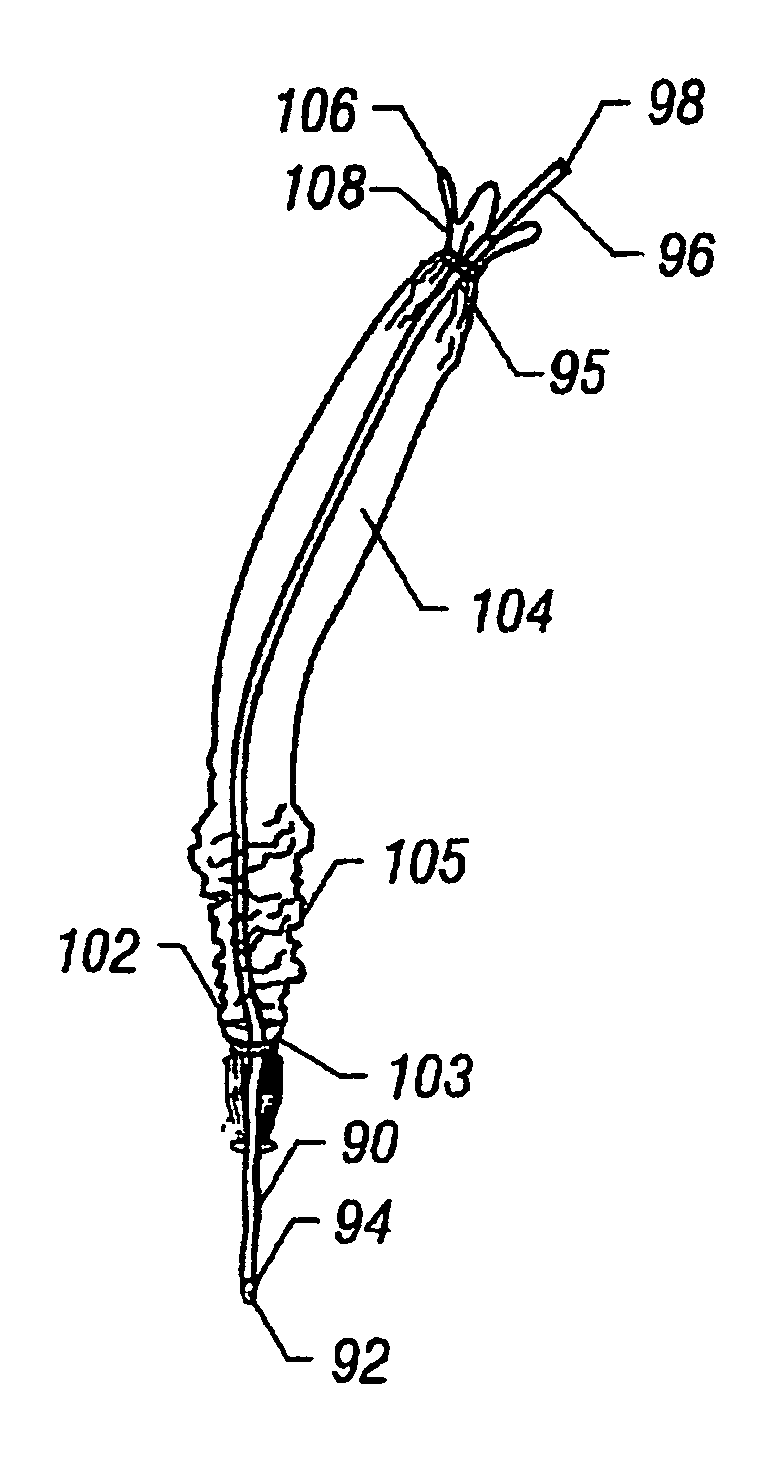
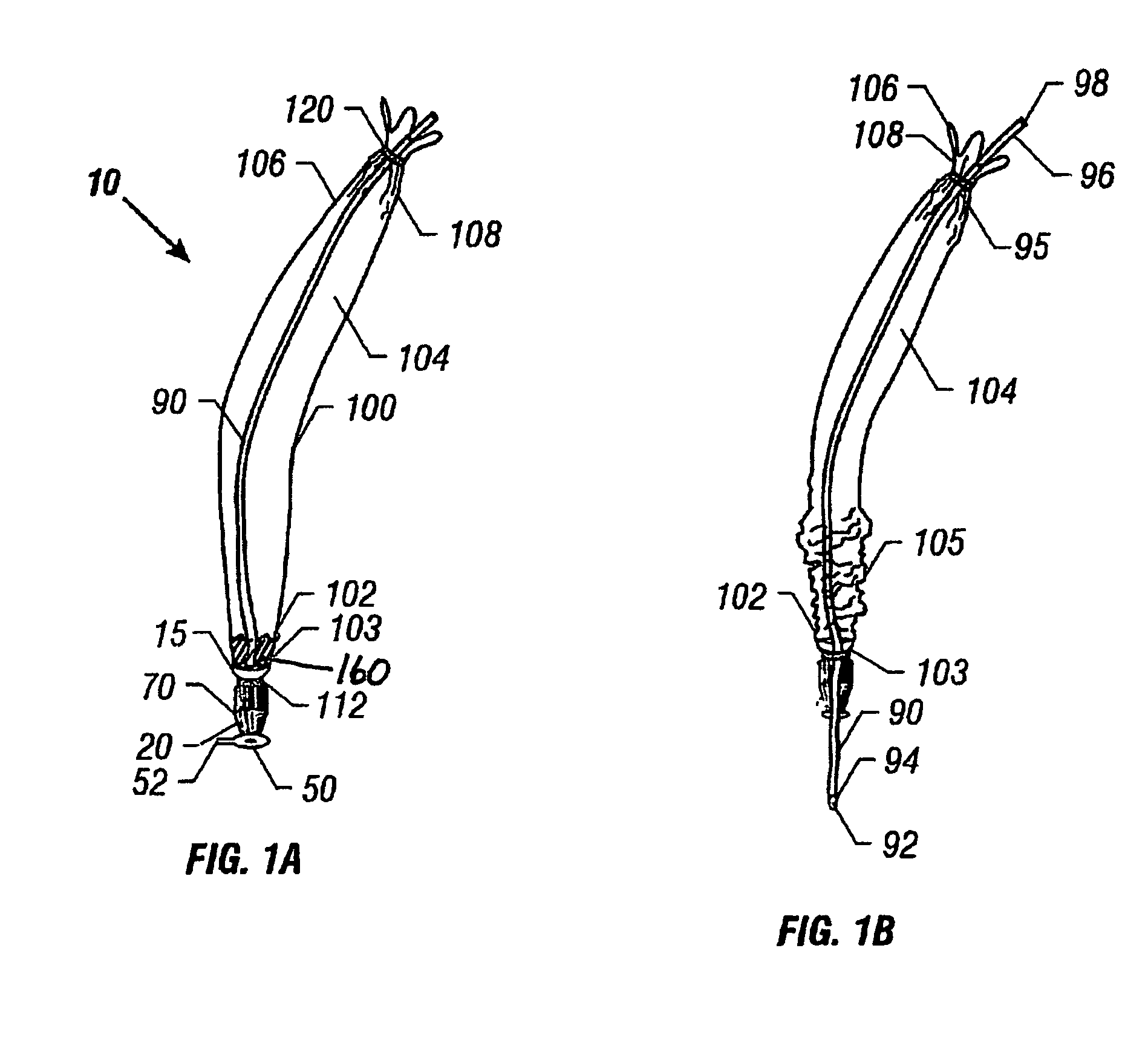
[0050]The present invention serves to address the shortcomings of conventional devices and assemblies on the market, and provide additional advantages and features not available to such conventional products. Referring to FIG. 1A, catheter device 10 includes a catheter introducer 15, a hydrophilic catheter 90, a thin-walled pliable sheath 100, and first and second sheath closures 112, 120. Optionally, a urine collection bag is pre-attached or can be attached by the user (FIGS. 8 and 9). Catheter 90 is preferably similar to, or the same as, a conventional hydrophilic urinary catheter, or it may be of any suitable hydrophilic urinary catheter design. All, or at least the portion of the catheter that is to be introduced into the urethra, is either coated with a hydrophilic material (e.g., PVC catheter coated with polyvinylpyrrolidone (PVP)), or is formed from a suitable hydrophilic material (e.g., silicone). In either case, the catheter is referred to as a “hydrophilic catheter” in thi...


PUM


Abstract

A disposable hydrophilic catheterization device for inserting a hydrophilic catheter into the urethra of an individual for the purpose of evacuating the bladder is disclosed. The catheter device includes a catheter introducer, a flexible hydrophilic catheter and a flexible thin-walled sheath. The sheath surrounds the urethra-insertable portion of the catheter, is adapted for containing a wetting liquid, and prevents pooling of the wetting liquid with collected urine. A leak-resistant diaphragm disposed within the catheter introducer is capable of being pierced by the catheter tip to form a leak-resistant orifice around the wetted hydrophilic catheter as it moves through the orifice.

Description

[0001]This application claims priority to U.S. Provisional Patent Application Ser. No. 60 / 708,893, filed Aug. 17, 2005, the content of which is hereby incorporated by reference in its entirety into this disclosure.BACKGROUND OF THE INVENTION[0002]1. Field of the Invention[0003]The present invention relates to catheter assemblies. More particularly, the present invention relates to catheter assemblies having multiple functions.[0004]2. Background of the Invention[0005]Short term, or repeated catheterization of an individual's urinary bladder is a common practice today for many persons who are in a hospital setting, a nursing home, doctor's office, rehabilitation facility or at home. For instance, a patient is sometimes catheterized to treat such conditions as urinary retention, the inability to evacuate urine, or for the purpose of obtaining a sterile urine specimen from a patient in a doctor's office.[0006]The need for intermittent catheterization of an individual sometimes arises d...

Claims


Application Information

Patent Timeline
Patent Type & Authority Patents(United States)
IPC IPC(8): A61M27/00
CPCA61M25/0017A61M25/0111A61M25/002A61M2025/0062
Inventor HOUSE, JAMIE GLEN
Owner COLORADO CATHETER
Why Eureka
Try Eureka