System and method for collecting exudates

a technology of exudate collection and exudate collection, which is applied in the direction of distillation regulation/control, siphon, packaged goods type, etc., can solve the problems of undesirable undesirable components and complex structures in canisters, and achieve the effects of reducing pressure, reducing bubble formation, and reducing pressure treatment system

Active Publication Date: 2012-01-24
3M INNOVATIVE PROPERTIES CO
View PDF149 Cites 34 Cited by
  • Summary
  • Abstract
  • Description
  • Claims
  • Application Information

AI Technical Summary

Benefits of technology

[0009]In still another illustrative embodiment, a collection canister is provided for use with a reduced pressure treatment system. The canister includes a collection chamber and an entry chamber positioned above the collection chamber. The entry chamber includes an open end and a closed end defined by an entry wall. The entry chamber further includes a floor separating the entry chamber from the collection chamber, the floor having an aperture allowing communication between the entry chamber and the collection chamber. An inlet is disposed in the entry wall of the entry chamber, and the inlet is adapted to be fluidly connected to a tissue site. An outlet is in communication with the collection chamber and is adapted to be fluidly connected to a reduced pressure source. A hydrophobic filter is positioned adjacent the outlet to prevent liquid from exiting the collection chamber through the outlet. A baffle having a base and a deflector plate is provided, and the base is removably positioned within the entry chamber through the opening of the entry chamber. The deflector plate of the baffle deflects liquid entering the entry chamber through the inlet from prematurely blocking the hydrophobic filter.
[0011]In another illustrative embodiment, a collection canister for use with a reduced pressure treatment system is provided. The canister includes a collection chamber and an entry chamber positioned above the collection chamber. The entry chamber has an open end and a closed end defined by an entry wall. The entry chamber further includes a floor separating the entry chamber from the collection chamber, the floor having an aperture allowing communication between the entry chamber and the collection chamber. An inlet is disposed in the entry wall of the entry chamber, and the inlet is adapted to be fluidly connected to a tissue site. An outlet is provided in communication with the collection chamber and is adapted to be fluidly connected to a reduced pressure source. A liquid-air separator is positioned adjacent the outlet to prevent liquid from exiting the collection chamber through the outlet, and a porous foam is positioned in the entry chamber to minimize bubble formation near the open end of the entry chamber.
[0012]In still another embodiment, a method for collecting exudate from a tissue site is provided. The method includes creating a reduced pressure within a collection canister to draw exudate from the tissue site to the collection canister. The collection canister includes an outlet and a liquid-air separator associated with the outlet. The method further includes minimizing deposition of protein from the exudate on the liquid-air separator.

Problems solved by technology

Complex structures and unnecessary components in the canisters are undesirable.

Method used


Image

  • System and method for collecting exudates
  • System and method for collecting exudates
  • System and method for collecting exudates

Examples


Embodiment Construction

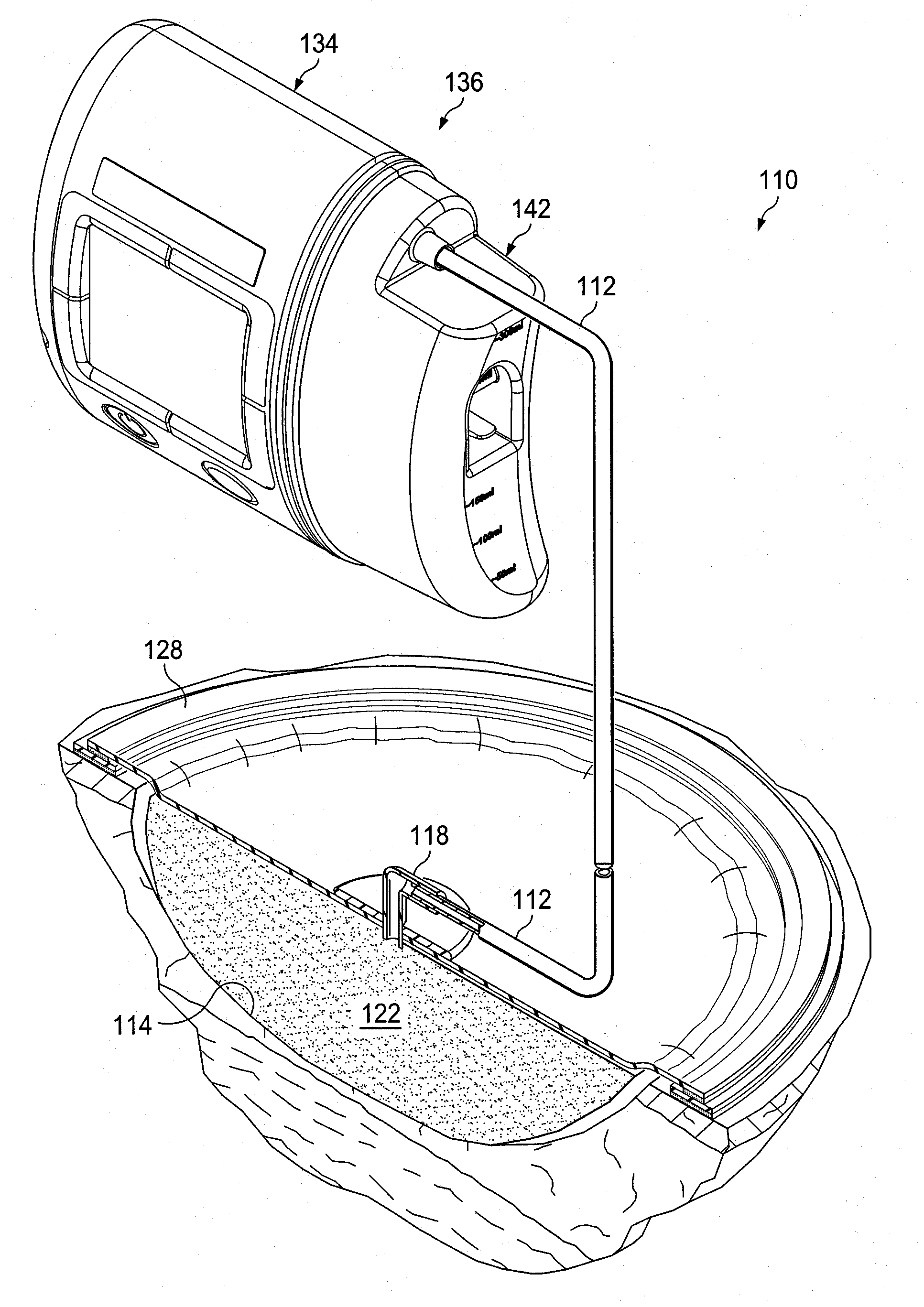
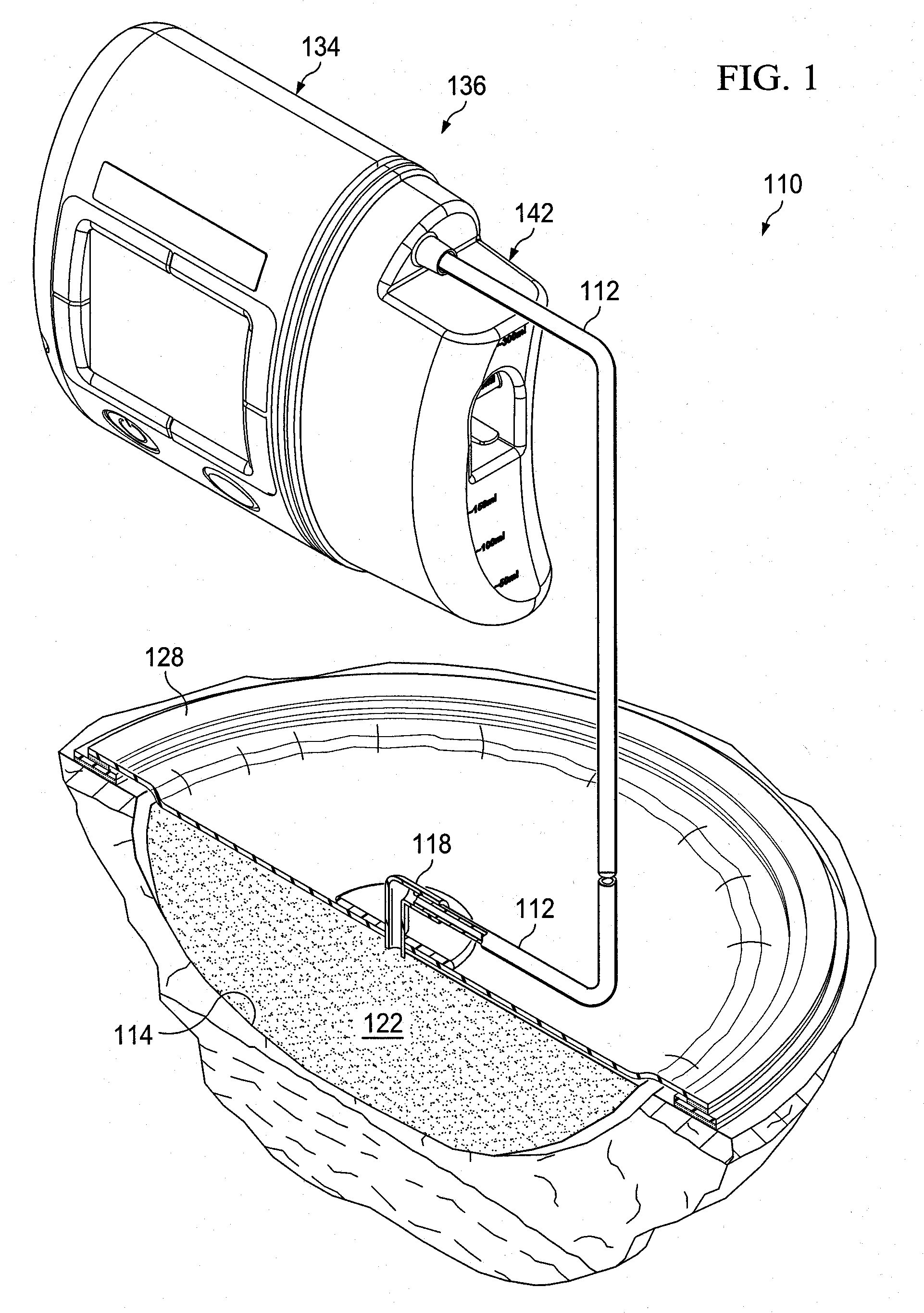
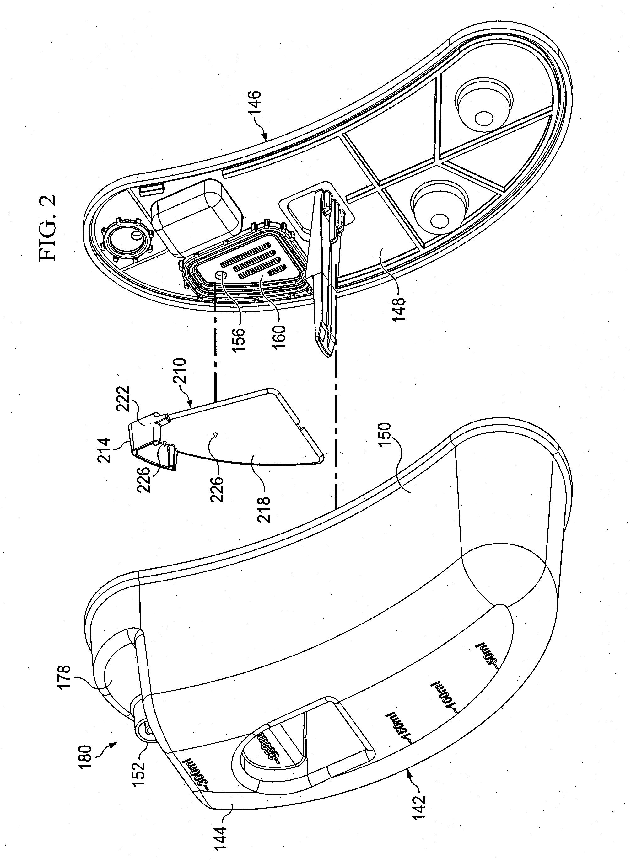
[0023]In the following detailed description of several illustrative embodiments, reference is made to the accompanying drawings that form a part hereof, and in which is shown by way of illustration specific preferred embodiments in which the invention may be practiced. These embodiments are described in sufficient detail to enable those skilled in the art to practice the invention, and it is understood that other embodiments may be utilized and that logical structural, mechanical, electrical, and chemical changes may be made without departing from the spirit or scope of the invention. To avoid detail not necessary to enable those skilled in the art to practice the embodiments described herein, the description may omit certain information known to those skilled in the art. The following detailed description is, therefore, not to be taken in a limiting sense, and the scope of the illustrative embodiments are defined only by the appended claims.

[0024]The term “reduced pressure” as used...


PUM

PropertyMeasurementUnit
pressureaaaaaaaaaa
areaaaaaaaaaaa
hydrophobicaaaaaaaaaa

Abstract

A reduced pressure treatment system includes a porous pad positioned at a tissue site and a canister having a collection chamber, an inlet, and an outlet. The inlet is fluidly connected to the porous pad. A reduced pressure source is fluidly connected to the outlet of the canister to such that fluid from the tissue site may be drawn into the collection chamber. A hydrophobic filter is positioned adjacent the outlet to prevent liquid from exiting the collection chamber through the outlet. A baffle is positioned within the canister to create a tortuous path between the inlet and the outlet to prevent premature blocking of the hydrophobic filter.

Description

CROSS-REFERENCE TO RELATED APPLICATIONS[0001]This application claims the benefit of U.S. Provisional Application No. 61 / 032,804 filed Feb. 29, 2008, which is hereby incorporated by reference.BACKGROUND OF THE INVENTION[0002]1. Field of the Invention[0003]The present invention relates generally to tissue treatment systems and in particular to systems and methods for collecting exudates.[0004]2. Description of Related Art[0005]Clinical studies and practice have shown that providing a reduced pressure in proximity to a tissue site augments and accelerates the growth of new tissue at the tissue site. The applications of this phenomenon are numerous, but application of reduced pressure has been particularly successful in treating wounds. This treatment (frequently referred to in the medical community as “negative pressure wound therapy,”“reduced pressure therapy,” or “vacuum therapy”) provides a number of benefits, including faster healing and increased formulation of granulation tissue....

Claims


Application Information

Patent Timeline
Patent Type & Authority Patents(United States)
IPC IPC(8): A61M1/00
CPCA61M1/0001A61M1/0088A61M1/0052A61M2205/7536A61M1/3627A61M2206/14A61M1/0031A61M2205/7563Y10T137/3185Y10T137/479Y10T137/7313Y10T137/4666A61M1/784A61M1/684A61M1/96A61M1/60A61M1/65A61M27/00A61M1/00A61M1/78A61M1/74
Inventor JAEB, JONATHAN PAULKELCH, RANDALL PAULLOCKE, CHRISTOPHER BRIANLUCKEMEYER, JAMESMCDANIEL, TERRIE LEAPHILLIPS, BRUCEROBINSON, TIMOTHY MARKJASWAL, ABHAYHIGLEY, KEVINSIMMONS, TYLER
Owner 3M INNOVATIVE PROPERTIES CO
Why Eureka
Try Eureka