Piston Assembly

a technology of pistons and assemblies, applied in the direction of machines/engines, mechanical equipment, liquid fuel engines, etc., can solve the problems of high gas temperature of piston assemblies used in heat engines/pumps for phes systems, and achieve the effects of low mass, low inertial force, and low cos

Inactive Publication Date: 2015-04-30
ENERGY TECH INST
View PDF7 Cites 41 Cited by
  • Summary
  • Abstract
  • Description
  • Claims
  • Application Information

AI Technical Summary

Benefits of technology

[0014]The reciprocating sleeve may have a thin wall such that the sleeve diameter: sleeve wall thickness ratio is at least 20:1, and preferably at least 30:1 or at least 50:1. Such a seal may be subject to lower inertial forces due to its low mass and with have lower thermal conductivity, which may assist to shield the seal arrangement from peak temperatures in the piston chamber.
[0015]The static seal may comprise a circumferentially segmented static seal. Because of the increased piston diameter, and the desirability of a lightweight sleeve / cylinder, it will be difficult to form the reciprocating sleeve (i.e. piston chamber) with perfect walls. A circumferentially segmented static seal ring with circumferentially extending segments, as opposed to a continuous ring, can conform better to the slight irregularities likely to be inherent in a larger diameter sleeve. Furthermore, the circumferentially extending segments enable the seal ring to accommodate a large amount of wear of the seal material without opening up any leakage gaps.
[0016]In such a static seal, the seal may comprise interlocking, circumferentially extending segments. The segments may be provided with respective mating ends such that they may (releasably) interlock with the ends of adjacent segments, or separate connectors may be used to interlock adjacent segment ends. They may be a drop-in / lift-out fit or a push-in / pull-out fit. Preferably, the ends may be provided with close-fitting male and female features which permit slight angular displacement and, ideally, relative radial translatory displacement in order to permit relative motion and to minimise gas bypass flow. Such features may incorporate slight elastic resilience to permit the interlocking features to be slightly elastically deformed so as to fit exactly with no gaps.
[0017]The static seal may comprise a multi-layered static seal comprising respective multiple layers axially disposed from one another. In that case, the interlocking, circumferentially extending segments, may be respectively staggered from one another in the adjacent multiple layers so as to minimise gas flow therethrough. By providing a labyrinthian flow path, undesired escaping gas flow through the seal is minimised. The seal may comprise axially extending locating elements that prevent relative rotation of the multiple layers. Relative rotation of the respective layers may be prevented by locking devices engaging between the respective layers (e.g. axially extending pins and notches). Springs may also be provided in the seal groove to force the seal radially outwards or inwards, depending whether it is sealing outwardly (against the sleeve interior) or sealing inwardly against the sleeve exterior.
[0018]In one embodiment, the static seal is mounted on the cylinder head for sealing engagement with an inner wall of the reciprocating sleeve. This arrangement has the advantages that it allows the incoming flow to cool adjacent walls near the seal, and placing the seal here results in a smaller dead volume adjacent to the compression or expansion space, which is thermodynamically preferable.

Problems solved by technology

For example, gas temperatures in piston assemblies used in heat engines / pumps for PHES systems may be especially demanding.

Method used


Image

  • Piston Assembly
  • Piston Assembly
  • Piston Assembly

Examples


Embodiment Construction

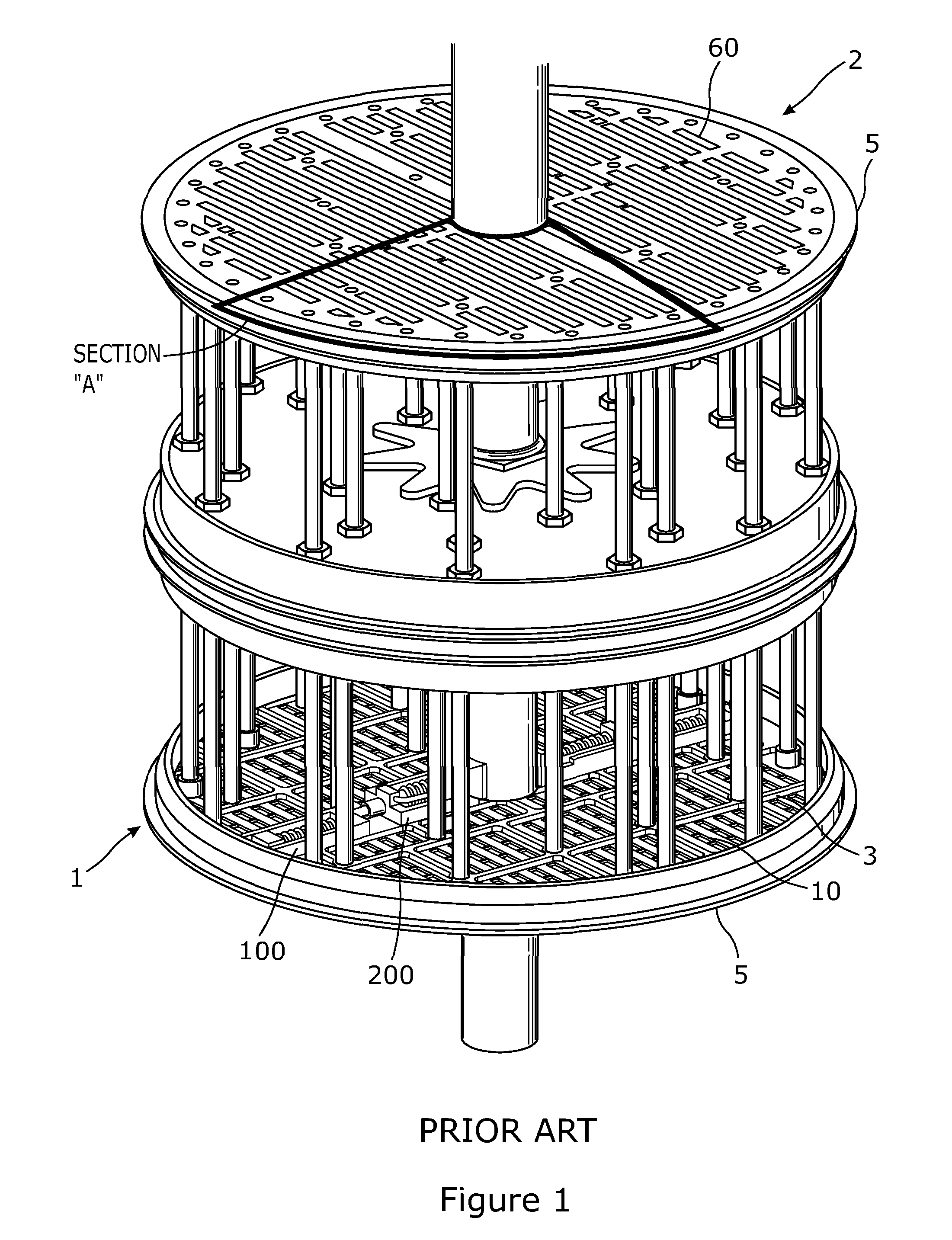
[0056]As discussed above, FIG. 1 shows a perspective view of a prior art double-acting piston mounted on a piston rod for reciprocation within a stationary piston chamber (not shown) towards and away from two opposed concentric cylinder heads (not shown) with a circumferential seal conventionally mounted around the piston exterior. Valving is provided in both piston faces in the form of multi-apertured screen valves.

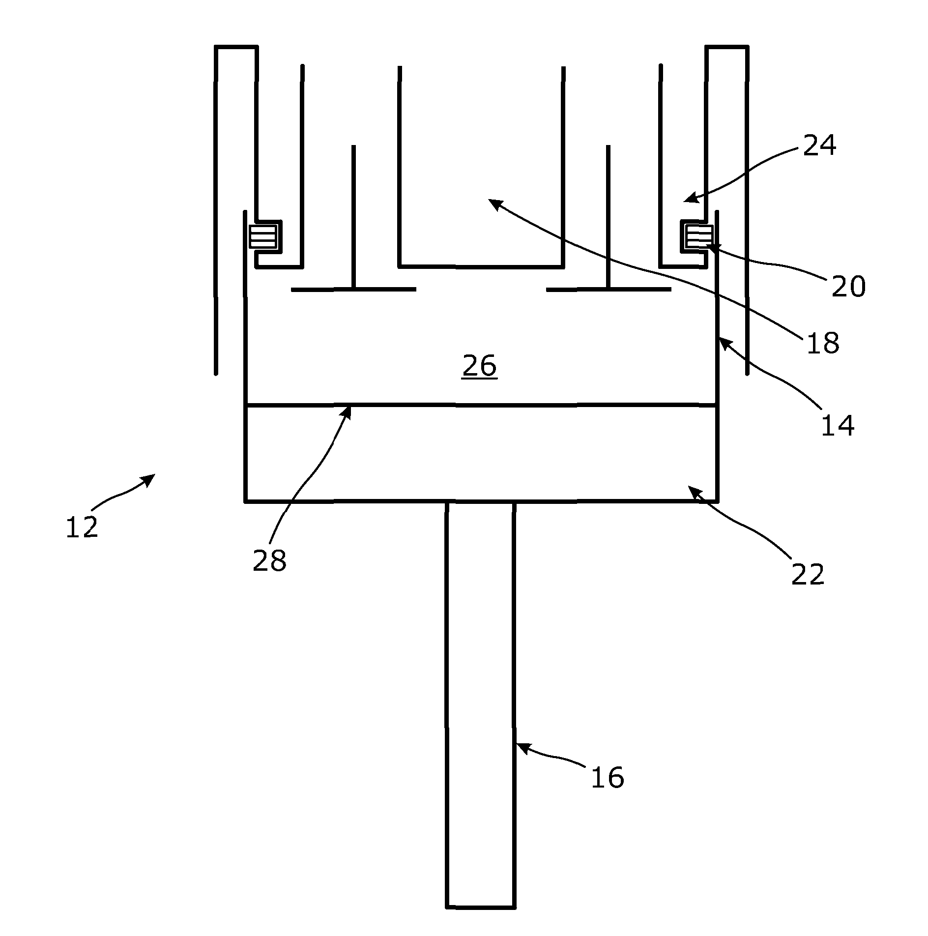
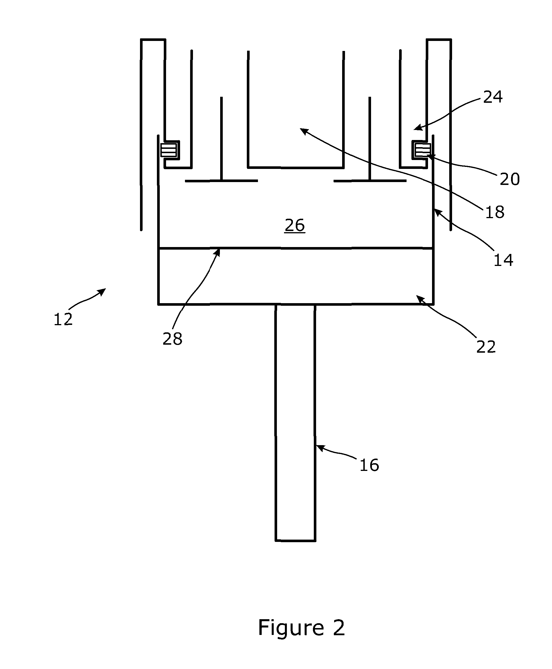
[0057]FIG. 2 shows a single-acting piston assembly 12 according to the present invention with a reciprocating cylindrical sleeve 14 mounted on a piston rod 16 for reciprocation towards and away from a cylinder head 18 containing valving. Such an assembly could be used in a heat pump or any other positive displacement, piston / cylinder based fluid or gas processing device such as, for example, a heat engine, gas expander or compressor.

[0058]The present Applicant has arrived at a piston / seal arrangement that may be used to make a piston assembly that can be large and / or ove...


PUM


Abstract

A piston assembly (12) comprising a reciprocating sleeve (14) incorporating an integral internal piston surface (28), which sleeve is slidably mounted upon a cylinder head (18) so as to define a piston chamber (26) therewith, the piston chamber being sealed in the vicinity of the cylinder head (18) by a circumferential static seal (20) that acts to seal against the reciprocating sleeve (14). The static seal (20) may occupy a horizontal plane and may include sacrificial wear zones and be formed from a graphite-based material. The piston assembly may be an oversquare assembly for use in an oil-free environment for processing high temperature gases, for example, a hot gas engine or heat pump or heat engine such as may be used in an energy storage system.

Description

TECHNICAL FIELD OF THE INVENTION[0001]The present invention relates generally to a piston assembly and to devices and systems including such an assembly. In particular, it relates to a piston assembly suitable for use in apparatus comprising a heat engine / heat pump, and especially energy storage systems comprising a heat engine / heat pump, where demanding operating conditions apply.BACKGROUND OF THE INVENTION[0002]In a heat engine / heat pump, the piston design needs to be optimised in order to secure energy efficiencies. Applicant's earlier application WO2006 / 100486 is directed to a heat pump with a high potential coefficient of performance. In that heat pump, an oversquare piston arrangement is used i.e. with a short piston stroke to a large piston diameter ratio and with compression valving or expansion valving provided in the piston face such that gas flow is directly through the piston face, so as to yield a high coefficient of performance. That application teaches a preferred eff...

Claims


Application Information

Patent Timeline
Patent Type & Authority Applications(United States)
IPC IPC(8): F16J1/00F16J15/16
CPCF16J15/16F16J1/00F04B53/14F16J1/001F16J10/02F04B53/143F04B53/162F02F11/00F02F11/005
Inventor HOWES, JONATHAN SEBASTIAN
Owner ENERGY TECH INST
Why Eureka
Try Eureka