XY stage

a technology of xy stage and xy body, which is applied in the field of xy stage, can solve the problems of low positioning accuracy, reduced positioning accuracy, and problematic vibration, and achieve the effect of sufficient suppression of vibration and easy control of movemen

Inactive Publication Date: 2010-02-02
NEC CORP
View PDF14 Cites 5 Cited by
  • Summary
  • Abstract
  • Description
  • Claims
  • Application Information

AI Technical Summary

Benefits of technology

[0024]An object of the present invention is to provide an XY stage capable of sufficiently suppressing a vibration generated after the high-speed movement of a movable section and capable of readily controlling the movement.

Problems solved by technology

Such an XY stage which two-dimensionally drives the movable section externally and indirectly via guides has a low level of positioning accuracy.
Therefore, a moment force is generated, causing a problematic vibration in a yawing direction.
In the wire bonder, although a bonding step is performed immediately after the XY stage is stopped, the vibration as described above leads to a reduced positioning accuracy or the like, thereby significantly degrading the bondability.
Accordingly, the downsizing of the XY stage itself is difficult to achieve.
Thus, it is difficult to sufficiently suppress the vibration caused by the high-speed movement of the movable stage.
Moreover, since a position detector is provided at a position above the movable table, the accuracy of the position detection is insufficient.
Thus, position control may be difficult to perform.
Hei 11-148984, although the intended objective can be achieved, it is difficult to suppress the vibration in the yawing direction caused by the high-speed movement of the movable stage.
In addition, these conventional XY stages have the problem of a narrow control band.
Therefore, the force of inertia of the movable section as a whole becomes large, and the vibration in the yawing direction or the like which resonates at a low frequency becomes a problem.

Method used


Image

  • XY stage
  • XY stage
  • XY stage

Examples


first embodiment

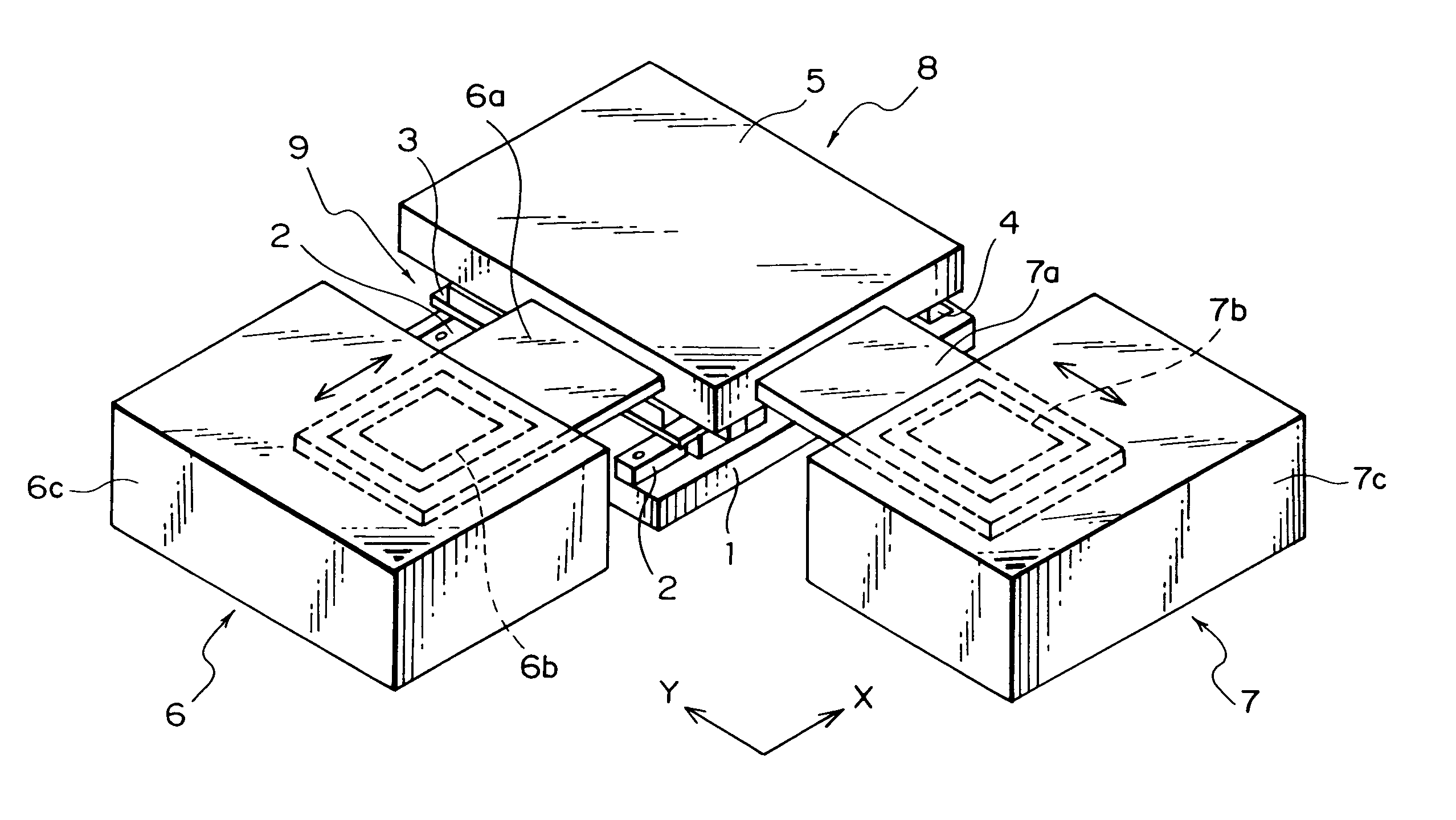
[0053]The preferred embodiments of the present invention will be described below specifically with reference to the accompanying drawings. FIG. 4 is a schematic diagram showing the structure of a wire bonder stage according to the present invention. FIG. 5 is a schematic diagram showing that a bonding head is attached onto the wire bonder stage shown in FIG. 4.

[0054]According to the present embodiment, two X-axis guides (first guide members) 2 are provided on a square-plate-shaped base 1, for example. The two X-axis guides 2 extend in a direction parallel to each other. This direction is referred to as an X-axis direction. An X-axis table (middle table) 3 is provided on the X-axis guides 2. X-axis follower sections (not shown) for following the X-axis guides 2 are provided on the lower surface of the X-axis table 3. The X-axis table 3 can be moved in the X-axis direction. Two Y-axis guides (second guide members) 4 extending in a Y-axis direction which is perpendicular to the X-axis ...

second embodiment

[0093]In the second embodiment, a plate-shaped cam follower guide (a first protruding guide member) 51 extending in the Y-axis direction is provided along an edge of the movable table 5 in the X-axis direction, and a plate-shaped cam follower guide (a second protruding guide member) 52 extending in the X-axis direction is provided along an edge of the movable table 5 in the Y-axis direction. In the present embodiment, although the cam follower guides 51 and 52 are connected with each other as shown in FIG. 19, they may be separated from each other.

[0094]An X-axis VCM 56 is disposed at the side of the edge of the movable table 5 on which the cam follower guide 51 is provided, and a Y-axis VCM 57 is disposed at the side of the edge of the movable table 5 on which the cam follower guide 52 is provided.

[0095]The X-axis VCM 56 includes a yoke section 56c with a shape of a rectangular tube. The yoke section 56c is fixed to a support (not shown), and has an opening passing therethrough in ...

third embodiment

[0104]In the present invention, two cam followers 56i and 56j are provided along an edge of the movable table 5 in the X-axis direction. The two cam followers 56i and 56j are disposed side by side in the X-axis direction. Two cam followers 57i and 57j are provided along an edge of the movable table 5 in the Y-axis direction. The two cam followers 57i and 57j are disposed side by side in the Y-axis direction.

[0105]No cam follower is provided at an edge portion of the X-axis movable element 56a. Instead, a plate-shaped cam follower guide 53 which protrudes downwardly from the edge portion is provided. The end surface of the cam follower guide 53 abuts on the movable table 5 between the cam followers 56i and 56j.

[0106]Likewise, no cam follower is provided at an edge portion of the Y-axis movable element 57a. Instead, a plate-shaped cam follower guide 54 which protrudes downwardly from the edge portion is provided. The end surface of the cam follower guide 54 abuts on the movable table...


PUM


Abstract

An XY stage comprises a base, a movable table which is disposed on the base so as to be movable in an X direction and a Y direction in an X-Y plane, and a work member which is provided on the movable table. The XY stage further comprises: a first linear motor for giving a driving force in the X direction to the movable table at the same height as the center of gravity of a movable section composed of the movable table and the work member; and a second linear motor for giving a driving force in the Y direction to the movable table at the same height as the center of gravity of the movable section.

Description

BACKGROUND OF THE INVENTION[0001]1. Field of the Invention[0002]The present invention relates to an XY stage which is suitable for a wire bonder, and more particularly to an XY stage which prevents a vibration caused by a high-speed movement and improves the controllability.[0003]2. Description of the Related Art[0004]When a large-scale integrated circuit (LSI) or a semiconductor device is connected to a lead frame using gold wires or the like, a wire bonder having an XY stage has been used. Such an XY stage is required to realize a high-speed and highly accurate positioning and to have a low level of residual vibration after driving / stopping.[0005]FIG. 1 is a schematic diagram illustrating a structure of a conventional wire bonder stage. FIG. 2 is a schematic diagram showing that a bonding head is attached onto the conventional wire bonder stage shown in FIG. 1.[0006]In the conventional wire bonder stage, two X-axis guides 102 are provided on a square-plate-shaped base 101. The two...

Claims


Application Information

Patent Timeline
Patent Type & Authority Patents(United States)
IPC IPC(8): A47B85/00H01L21/60B23Q15/24H01L21/68
CPCH01L24/78H01L24/45H01L2224/45144H01L2224/78801H01L2924/01004H01L2924/01006H01L2924/01039H01L2924/01079H01L2924/01082H01L2924/14H01L2924/00014H01L2924/01005H01L2924/01019H01L2924/01033H01L2224/48
Inventor SHOJI, MAHOKUBOTA, NORIYUKIOISHI, JUNICHIRO
Owner NEC CORP
Why Eureka
Try Eureka