Anti-jamming system

a technology of anti-jamming and anti-reflection, which is applied in the direction of radio transmission, electrical equipment, transmission, etc., can solve the problem of high demands of known anti-jamming systems

Active Publication Date: 2014-05-22
SEMICON IDEAS TO MARKET ITOM
View PDF1 Cites 6 Cited by
  • Summary
  • Abstract
  • Description
  • Claims
  • Application Information

AI Technical Summary

Benefits of technology

[0008]The invention is based on the recognition that a narrowband selection of an incoming jamming signal can be obtained by using a zero IF PLL jamming signal receiver being tuned to receive said jamming signal, followed by a replica jamming signal generator. Such zero IF receiver not only demodulates the incoming jamming signal into its base band component or envelope signal thus allowing for a narrowband baseband selection thereof, it also preserves the exact carrier frequency and phase of the jamming signal. With these preserved signal components a replica jamming signal can be generated, which accurately corresponds to the original jamming signal.
[0009]According to the invention, the suppression of the jamming signal received at the signal combining means of the anti jamming system is obtained by including the zero IF PLL jamming signal receiver and the replica jamming signal generator in a negative jamming signal feedback loop having input and outputs coupled to said signal combining means. To obtain an effective reduction of the incoming jamming signal, the phase and gain requirements of the loop are easy to comply with in that the open loop gain of the jamming signal in the feedback loop only has to be sufficiently large, whereas the loop only has to reverse the signal phase, i.e. effectuate a 180° phase shift, of the jamming signal compared to the phase of the incoming jamming signal. This allows for a robust implementation of the anti jamming system.

Problems solved by technology

The concept of the known anti jamming system is highly demanding with regard to the accuracy and performance of the circuitry needed, such as e.g. the stability of the notch filters and oscillators.

Method used


Image

  • Anti-jamming system
  • Anti-jamming system
  • Anti-jamming system

Examples


Embodiment Construction

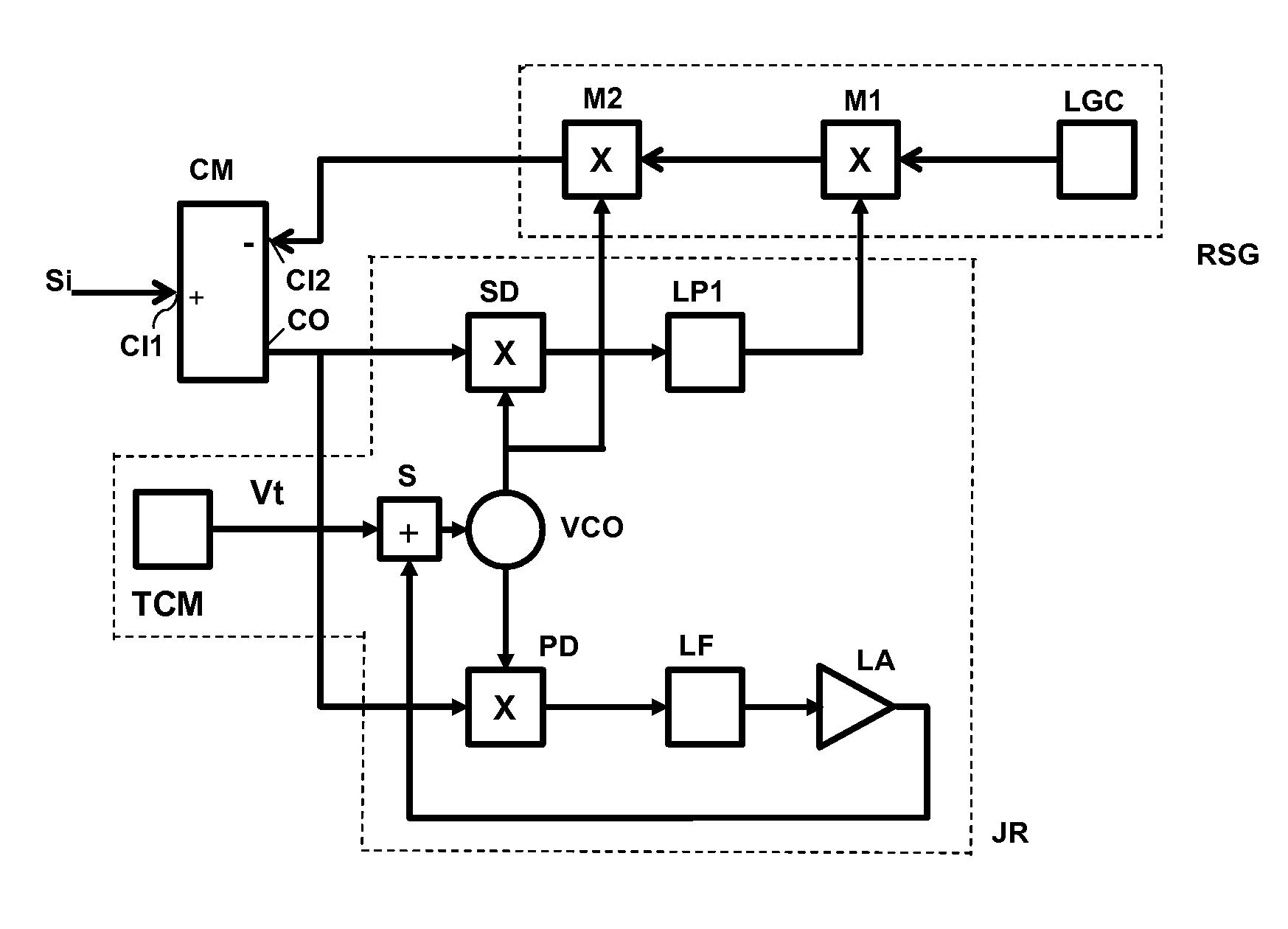
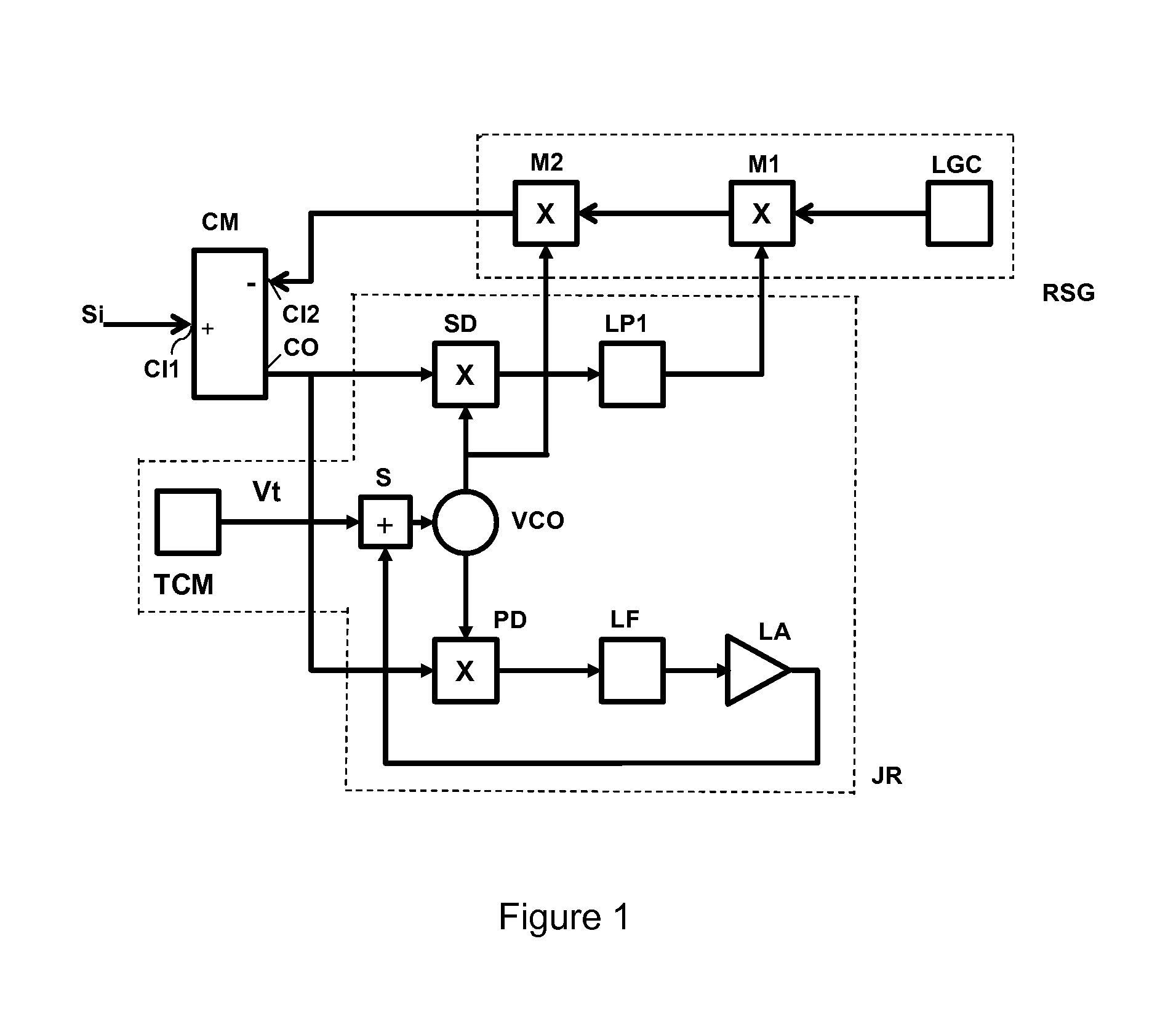
[0040]FIG. 1 shows an anti jamming system having signal combining means CM, receiving at a first input CI1 an input signal Si including a jamming signal. An output CO of the signal combining means CM is coupled to a jamming signal receiver JR for receiving said jamming signal followed by a jamming signal replica generator RSG for generating a replica jamming signal. An output of the jamming signal replica generator RSG is negatively coupled to a second input of the signal combining means CM and forms therewith a negative jamming signal feedback loop for feedback suppression of said jamming signal from the output CO of the signal combining means CM back to the second input thereof. This results in a feedback suppression of a received jamming signal in the signal combining means CM, which increases with the open loop gain as provided by the jamming signal receiver JR and the jamming signal replica generator RSG, preventing strong jamming signals from occurring at the output CO of the ...


PUM


Abstract

An anti-jamming system includes a tunable negative jamming signal feedback loop for feedback suppression of a received jamming signal. The system includes a zero IF phase locked loop (PLL) jamming signal receiver having a synchronous demodulator and a phase detector. A VCO is included in the PLL, as well as a phase detector and a loop filter. A replica jamming signal generator includes a tracking modulator with a baseband signal input coupled to an output of a synchronous demodulator in the receiver and a carrier input provided by the VCO. An output of the tracking modulator is negatively fed back to the input of the receiver to suppress the jamming signal in the received input.

Description

[0001]This invention is a Continuation of U.S. patent application Ser. No. 12 / 682,251, filed 8 Jul. 2010, which claims the benefit of EP patent application 07019800.7 filed 10 Oct. 2007.BACKGROUND AND SUMMARY OF THE INVENTION[0002]The invention relates to an anti jamming system with improved anti jamming techniques and, more specifically, to a technique for improved suppression of (suppressed) carrier modulated jamming signals, such as occurring in e.g. RF broadcast radio and TV systems, spread spectrum transmission systems, such as the Global Positioning System (GPS) and / or communication systems, such as GSM and CDMA and / or radar systems.[0003]An anti jamming system for improved anti jamming of wideband radar systems is known, e.g. from UK Patent Application GB 2 215 565. This known anti jamming system is applied in a superheterodyne RF receiver using in an intermediate frequency (IF) signal path thereof an IF notch filter per each jamming signal. Suppression of an incoming first j...

Claims


Application Information

Patent Timeline
Patent Type & Authority Applications(United States)
IPC IPC(8): H04K3/00
CPCH04K3/228
Inventor KASPERKOVITZ, WOLFDIETRICH GEORG
Owner SEMICON IDEAS TO MARKET ITOM
Why Eureka
Try Eureka