Receiver configuration for a control unit in a vehicle and method for generating a synchronization pulse

a technology of synchronization pulse and control unit, which is applied in the direction of data switching network, pedestrian/occupant safety arrangement, speed/phase control of synchronization signal, etc., can solve the problem of low tolerance and achieve the effect of low electromagnetic emission

Active Publication Date: 2018-04-10
ROBERT BOSCH GMBH
View PDF8 Cites 0 Cited by
  • Summary
  • Abstract
  • Description
  • Claims
  • Application Information

AI Technical Summary

Benefits of technology

[0005]An example receiver configuration according to the present invention for a control unit in a vehicle and an example method according to the present invention for generating a synchronization pulse may have the advantage that a preferably low electromagnetic emission is achievable, in particular in the spectral range of the signal transmission (100 kHz to 300 kHz) due to the sinusoidal formation of the synchronization pulse within the predefined limits.
[0011]In one advantageous embodiment of the receiver configuration according to the present invention, a first digital trigger circuit and a first digital / analog converter may generate and output a generally sinusoidal reference current to the current source. A second digital trigger circuit and a second digital / analog converter may also generate and output an generally sinusoidal reference current to the current source. This advantageously permits a very robust implementation of the synchronization pulse and a reduced electromagnetic emission. Furthermore, the triggering of the synchronization pulse may be shifted completely to the digital part of the circuit, which may result in an area-efficient approach per unit of area, due to the ever advancing scaling of the semiconductor technology. A voltage supply for the receiver may be decoupled from the databus during the synchronization pulse, while the voltage generator is activated for generating the synchronization pulse. Since the voltage generator includes a current source and a current sink for generating the synchronization pulse, the need for an additional switch in series with the current source and the current sink may be omitted.
[0012]In another advantageous embodiment of the receiver configuration according to the present invention, a joint digital trigger circuit and a joint digital / analog converter may generate and output a generally sinusoidal reference current to the current source and to the current sink. The number of components of the voltage generator may be reduced and layout area may be saved by joint utilization of the digital trigger circuit and the digital / analog converter.
[0013]The shape of the synchronization pulse may be stored either in the digital part or in the digital trigger circuit or it may be calculated with the aid of an algorithm. The digital / analog converter generates a reference current from an N-bit data word, this reference current being conducted via the current source and the current sink to the databus, charging and discharging the load applied to the databus. To generate a generally sinusoidal synchronization pulse, i.e., a sinusoidal or approximately sinusoidal synchronization pulse, both the current source and the current sink are triggered in a sinusoidal or approximately sinusoidal form. The resolution of the data word may be selected for emission reasons, in such a way that the synchronization pulse may be imaged without any significant discontinuities. The capacitance of the bus load integrates the bus current and thereby smoothes the voltage on the databus.

Problems solved by technology

However, the lowest tolerances and thus the most reliable regulation are to be expected in the vicinity of the maximum of the pulse voltage since the voltage here is subject to the smallest changes.

Method used


Image

  • Receiver configuration for a control unit in a vehicle and method for generating a synchronization pulse
  • Receiver configuration for a control unit in a vehicle and method for generating a synchronization pulse
  • Receiver configuration for a control unit in a vehicle and method for generating a synchronization pulse

Examples


Embodiment Construction

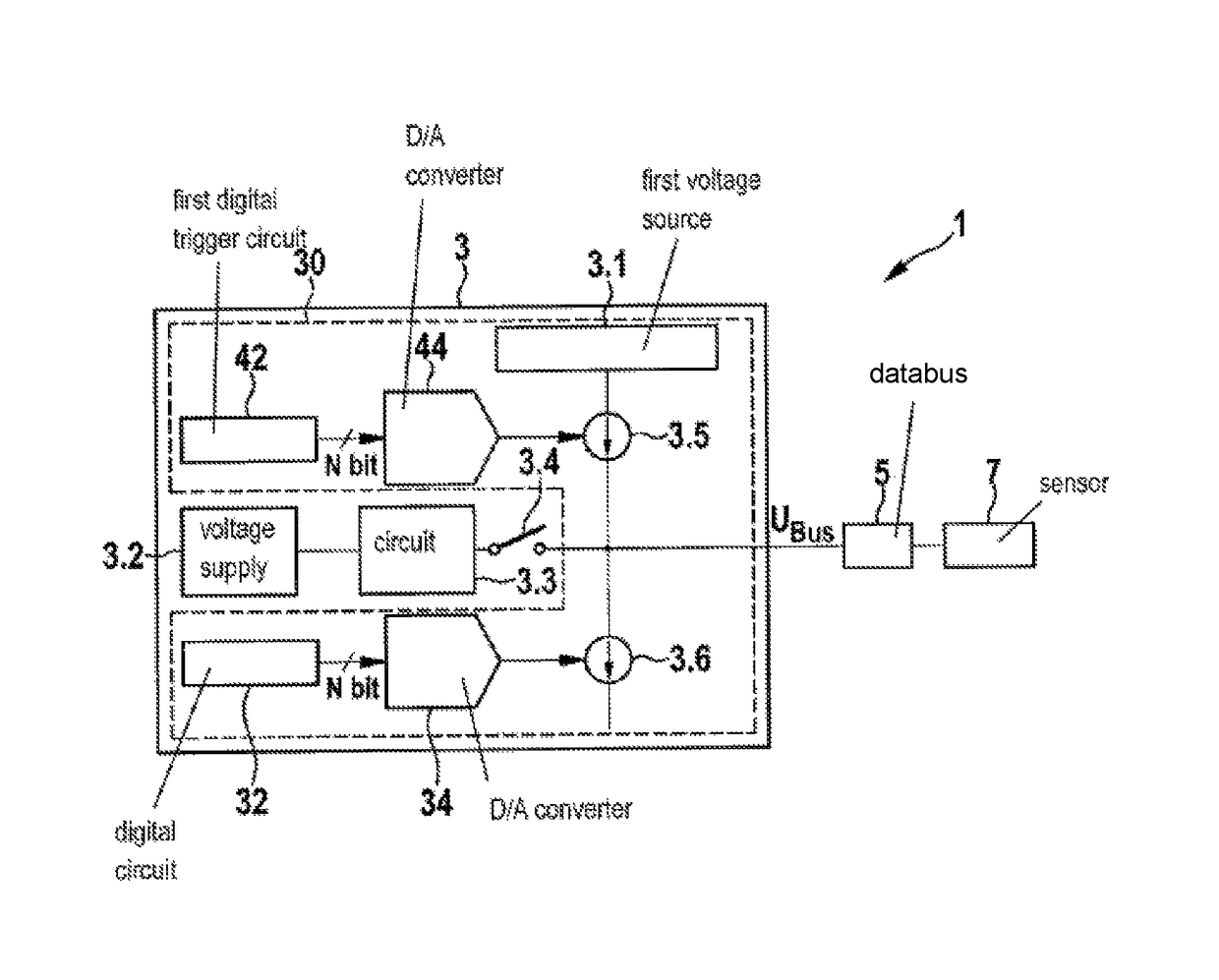
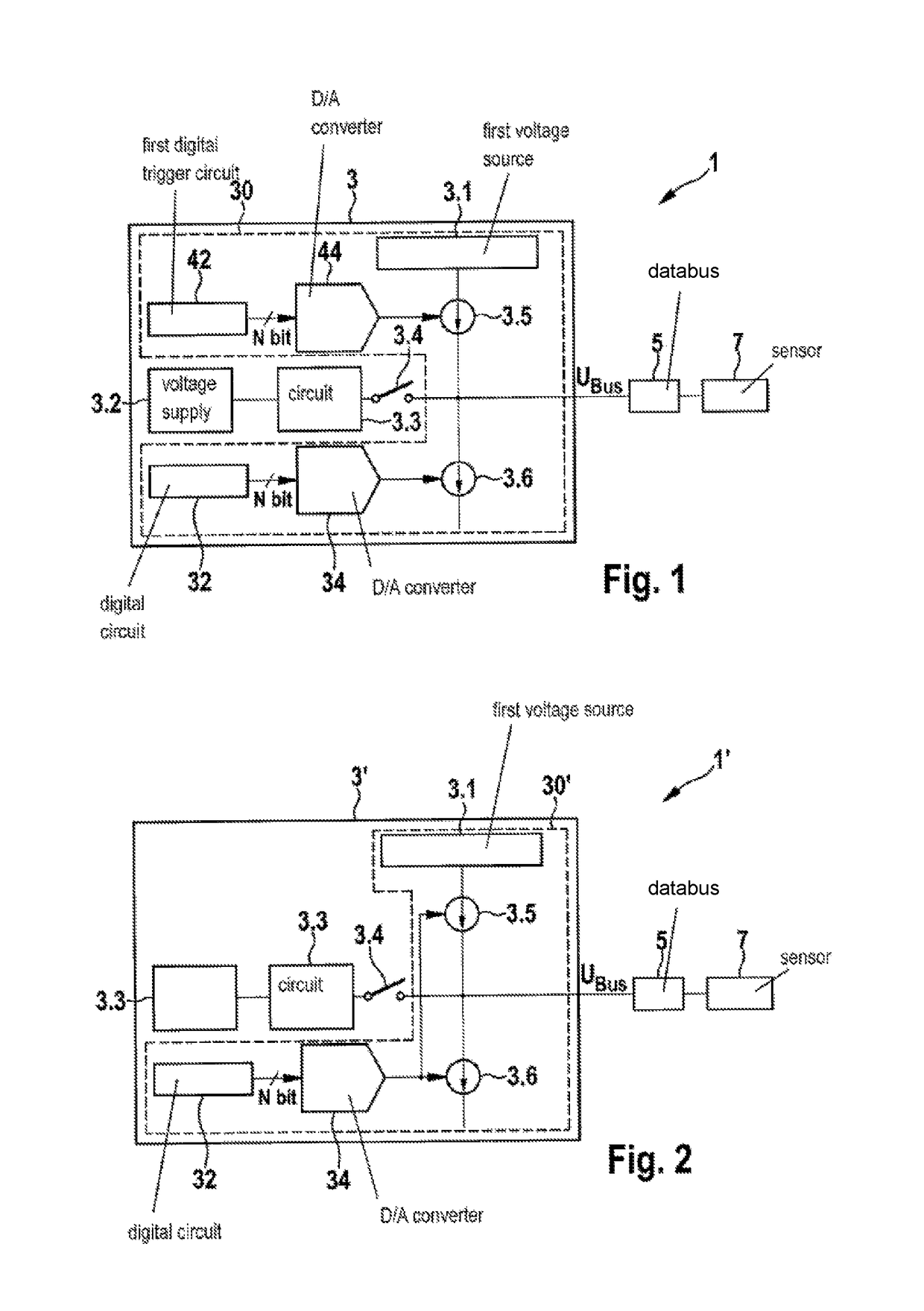
[0025]As is shown in FIGS. 1 and 2, sensor configurations 1, 1′ include a databus 5, at least one sensor 7 and one exemplary embodiment of a receiver configuration 3, 3′ according to the present invention for a control unit in a vehicle. Receiver configurations 3, 3′ according to the present invention each include a voltage generator 30, 30′ for generating a synchronization pulse Psync having a first voltage source 3.1, a current source 3.5 and a current sink 3.6. According to the present invention, voltage generator 30, 30′ generates a synchronization pulse Psync via current source 3.5 and current sink 3.6 by charging and / or discharging a bus load essentially as a sinusoidal oscillation.

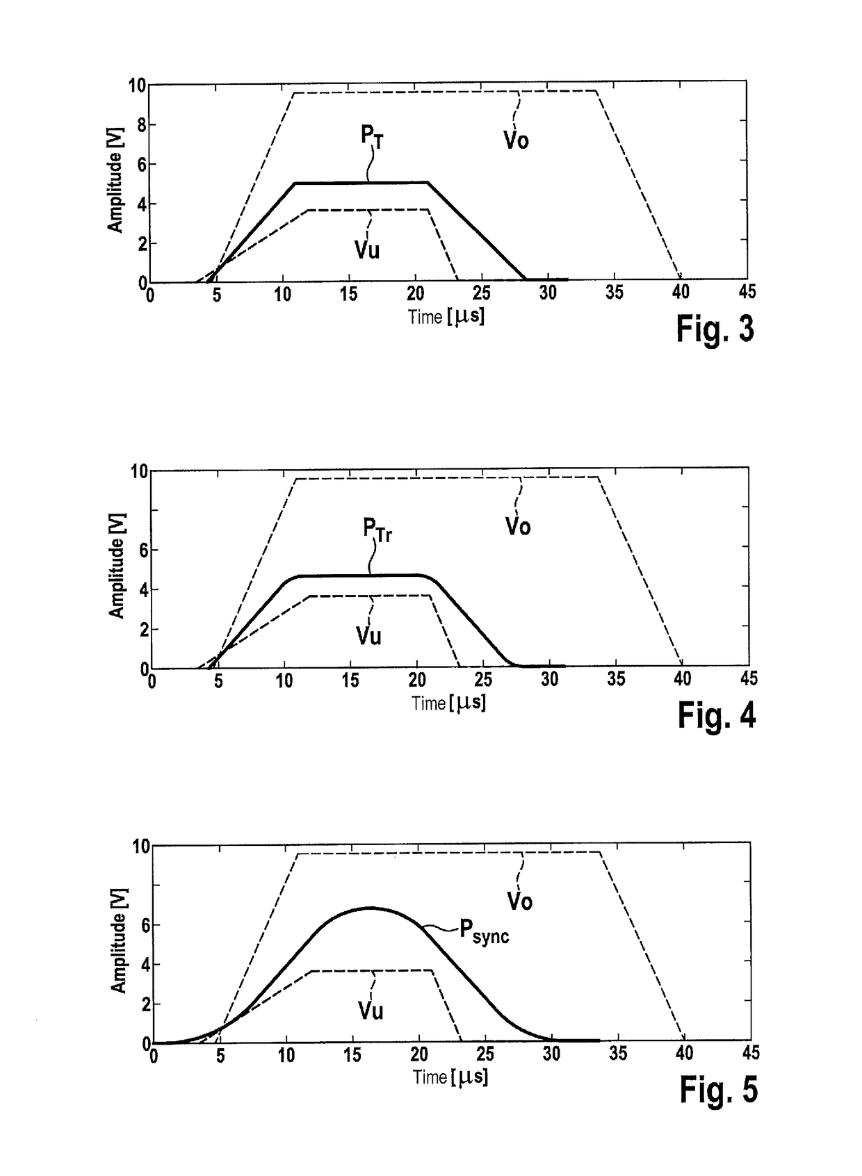
[0026]As is shown in FIG. 5, voltage generator 30, 30′ generates a synchronization pulse Psync within predefined specification limits Vo, Vu having a predefined shape and predefined time characteristic. Receiver configuration 3, 3′ outputs synchronization pulse Psync for synchronization of a subsequ...


PUM


Abstract

A receiver configuration for a control unit in a vehicle having a voltage generator for generating a synchronization pulse, which includes a first voltage source, a current source and a current sink, the voltage generator generating the synchronization pulse within predefined specification limits having a predefined shape and a predefined time behavior, and the receiver configuration outputting the synchronization pulse for synchronizing a signal transmission via a databus to at least one sensor. A method is also provided for generating a synchronization pulse. The voltage generator generates the synchronization pulse via the current source and the current sink by charging and / or discharging a bus load essentially as a sinusoidal oscillation.

Description

FIELD[0001]The present invention relates to a receiver configuration for a control unit in a vehicle and a corresponding method for generating a synchronization pulse.BACKGROUND INFORMATION[0002]For transmitting sensor data to a central control unit (ECU) in a vehicle, peripheral sensors for occupant protection systems generally use current interfaces (e.g., PAS4, PSI5). In current interfaces of the latest generation (PSI5), bus operation, including multiple sensors on one receiver, is made possible with the aid of synchronization. A working clock pulse in the form of a voltage pulse is generated by the central control unit (ECU) for the synchronization function. This voltage pulse is detected by the sensors on the bus and identifies the start of a new cycle for data transmission. This voltage pulse is known as the synchronization pulse and is formed with the aid of current sources and current sinks, which charge and discharge the bus load. This voltage pulse is typically repeated e...

Claims


Application Information

Patent Timeline
Patent Type & Authority Patents(United States)
IPC IPC(8): B60R21/01H04L7/04H04L12/40
CPCB60R21/01H04L7/04H04L12/40006H04L2012/40273H04L2007/047H04L7/044H04L25/03834H04Q9/04
Inventor WEISS, TIMOSIEMSS, MATTHIASWEISS, GUENTERMOMENI, MASSOUD
Owner ROBERT BOSCH GMBH
Why Eureka
Try Eureka