
Device and method for attenuating radiation from in vivo electrical devices

a technology of in vivo electrical devices and electromagnetic radiation, which is applied in the direction of nuclear engineering, nuclear elements, synthetic resin layered products, etc., can solve the problems of reducing the amount of electromagnetic radiation emitted, affecting the function of electrical devices, and affecting the capacity of external collection units to receive signals. , to achieve the effect of lowering the amount of electromagnetic radiation

Inactive Publication Date: 2007-01-09
GIVEN IMAGING LTD
View PDF6 Cites 27 Cited by
  • Summary
  • Abstract
  • Description
  • Claims
  • Application Information

AI Technical Summary

Benefits of technology

[0007]Embodiments of the present invention lower the amount of electromagnetic radiation emitted from in vivo electrical devices which reaches the environment external to the body and / or outside of or beyond an external collection units.
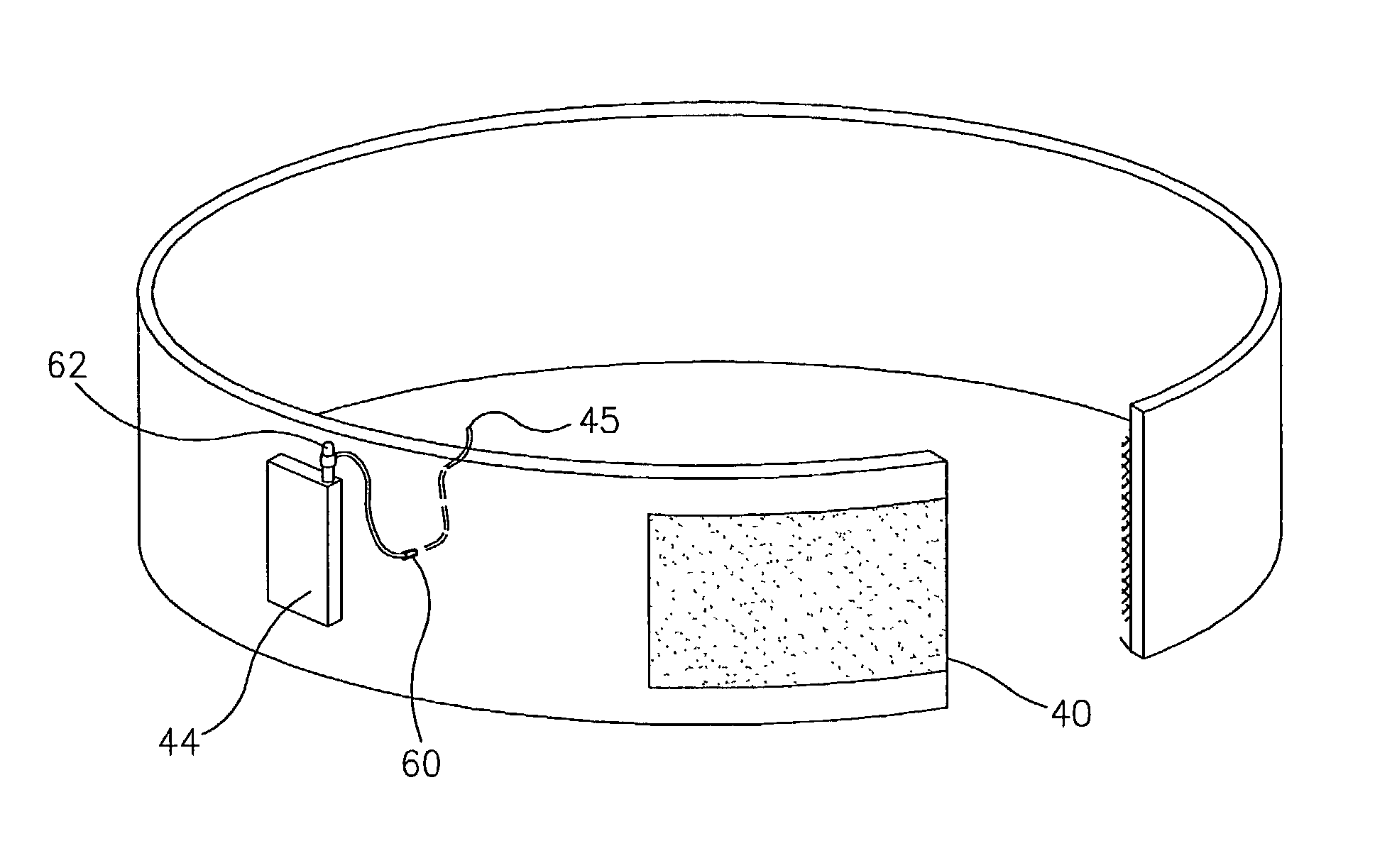
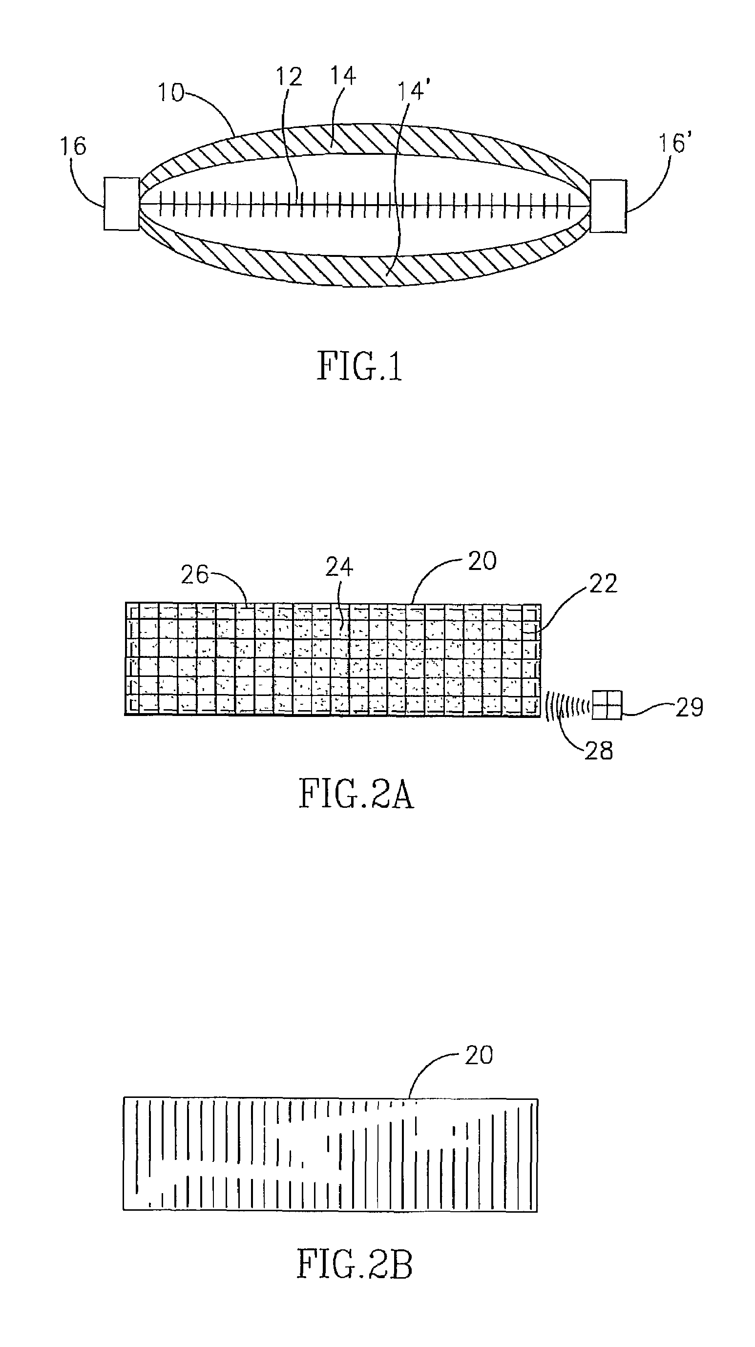
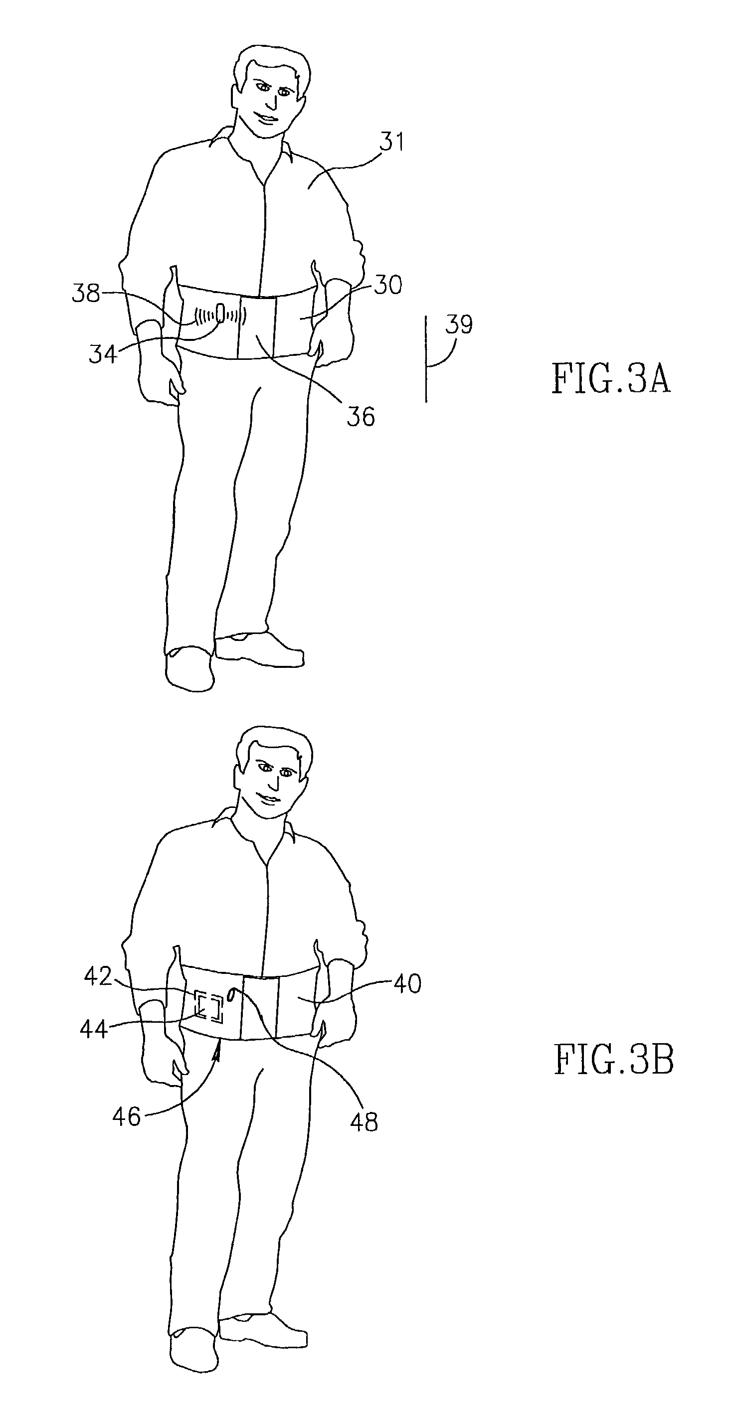
[0014]The garment is worn on the outside of the body, typically covering the area of the body corresponding to the location of the in vivo electrical device that emits electromagnetic radiation. The shielding layer in the garment attenuates the electromagnetic radiation emitted by the electrical device, which is radiated into the environment external to the body or its vicinity. In some embodiments, the garment includes a holder or strap, typically on its inner side, for an external collection unit in a position typically corresponding to the location of the in vivo electrical device in the body, thereby permitting the external collection unit to be exposed to the electromagnetic radiation emitted by the electrical device without interference from the shielding layer in the garment.

Problems solved by technology

While reducing electromagnetic radiation emissions from these electrical devices could be possible, such reduction may impair the function of the electrical device or the capacity of external collection units to receive the signals transmitted by the electrical devices.

Method used


Image

  • Device and method for attenuating radiation from in vivo electrical devices
  • Device and method for attenuating radiation from in vivo electrical devices
  • Device and method for attenuating radiation from in vivo electrical devices

Examples


Embodiment Construction

[0024]In the following description, various aspects of the present invention will be described. For purposes of explanation, specific configurations and details are set forth in order to provide a thorough understanding of the present invention. However, it will be apparent to one skilled in the art that the present invention may be practiced without the specific details presented herein. Furthermore, well-known features may be omitted or simplified in order not to obscure the present invention.

[0025]Embodiments of the present invention relate to a system and method of attenuating the amount of electromagnetic radiation from in vivo electrical devices which reach the environment external to the body and / or external collection units.

[0026]In accordance with an embodiment of the present invention, the body into or onto which an electrical device has been implanted, inserted, ingested or attached is fitted with a garment containing a shielding layer comprising a conductive material or ...


PUM

PropertyMeasurementUnit
Sound / signal amplitudeaaaaaaaaaa

Abstract

A garment and method for reducing electromagnetic radiation produced by a transmitting device typically located inside a body. The garment may include material to prevent or lower electromagnetic radiation. A method for using such a garment to lower electromagnetic emissions is described.

Description

PRIOR PROVISIONAL APPLICATION[0001]The present application claims benefit from prior provisional application No. 60 / 302,672 entitled “ATTENUATING RADIATION FROM IN VIVO ELECTRICAL DEVICES” and filed on Jul. 5, 2001.FIELD OF THE INVENTION[0002]The present invention relates to a system and method of attenuating electromagnetic radiation from electrical and electronic in vivo devices.BACKGROUND OF THE INVENTION[0003]Certain medical treatments, therapies or diagnostic procedures call for the implantation, insertion, ingestion or attachment of an electrical or electronic device (hereinafter, collectively an electrical device) into the bodies of the subjects of such treatments, therapies or diagnostic procedures. Certain electrical devices emit electromagnetic radiation either as a by-product of their designated function or as part of the transmission by such electrical devices of data, images or other information to antennas or other data collection units outside the body (such external ...

Claims


Application Information

Patent Timeline
IPC IPC(8): G21F3/02A41D13/015A61N5/02B32B27/04A41D13/05A41D31/00A41F9/00B32B5/26D02G3/44D03D15/00G21F1/08
CPCA41D13/0525B32B5/26D02G3/441D03D11/00D03D15/00G21F1/08G21F3/02A41F9/00Y10T428/2907D10B2101/20D10B2201/02D10B2331/02D10B2401/16D10B2501/04D10B2509/00Y10T442/259Y10T442/652Y10T442/3415Y10T442/654Y10T442/618Y10T442/3423Y10T442/656Y10T442/3374Y10T442/2475Y10T442/651Y10T442/653Y10T442/339Y10T442/655Y10T442/3382Y10T442/3431Y10T442/3902Y10T442/335D03D15/25B32B2307/212B32B2437/00B32B15/14B32B15/20
Inventor GLUKHOVSKY, ARKADY
Owner GIVEN IMAGING LTD
Learn More