Ground milling machine and method for adjusting the stripping plate of a ground milling machine

a ground milling machine and stripping plate technology, which is applied in the field of ground milling machines, can solve the problems of heavy wear on the working device of the milling drum, for example, the round shaft chisel, and the process is very time-consuming and needs to be repeated regularly, so as to achieve the effect of reliable method performan

Active Publication Date: 2018-06-19
BOMAG
View PDF12 Cites 1 Cited by
  • Summary
  • Abstract
  • Description
  • Claims
  • Application Information

AI Technical Summary

Benefits of technology

[0009]The object of the present invention is to provide an option of improving the handling of such a stripping plate and, in particular, of enabling trouble-free operation, in particular reliable height adjustment.
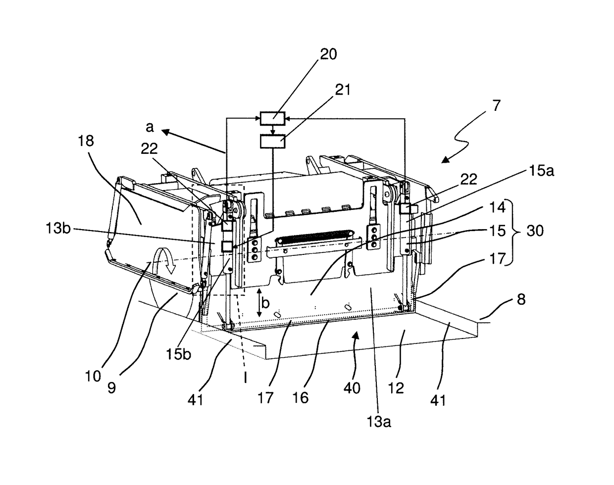
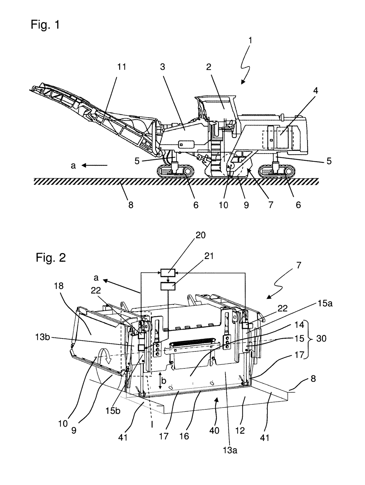
[0010]One aspect of the present invention is the fact that a monitoring device having at least one sensor is provided which is configured for monitoring the adjustment of the stripping plate. Specifically, the adjustment position and / or the adjustment speed are monitored. Thus, the monitoring device is basically configured in such a way that it detects the position and / or adjustment speed of the stripping plate by means of the at least one sensor. Adjustment of the stripping plate may include height adjustment of the stripping plate on the milling drum box, particularly the height adjustment of the bottom plate relative to the upper plate, and, additionally or alternatively, the pivot-up and pivot-down movement of the stripping plate relative to the remaining milling drum box, for example, in the case of maintenance work. The term monitoring device refers to the entirety used for detecting the adjustment position and / or the adjustment speed of the stripping plate. A further aspect of the present invention lies with a control device controlling the actuation movement of at least one of the actuators depending on the adjustment of the stripping plate determined by the monitoring device. Control of the adjustment movement is effected such that the stripping plate is adjusted in a most parallel manner, i.e., that ideally the at least two actuators are activated in such an inter-coordinated manner that, for example, a height adjustment of the stripping plate, and particularly of the bottom plate relative to the upper plate, is effected continuously on both sides without the stripping plate getting jammed, for example. If possible, also the pivot-up and pivot-down movement of the stripping plate is to be effected as continuously as possible in order to ensure reliable engagement of possible present locking elements, which lock the stripping plate in the pivot-down position on the milling drum box, on both sides in a safe manner. One aspect of the present invention thus lies with the interplay between the monitoring device and the control device, wherein the control device controls the adjustment process of the stripping plate depending on the sensor data determined by the monitoring device, in order to enable a continuous, synchronous and inter-coordinated operation of the at least two actuators of the stripping plate. Changes of friction values or comparable effects, which change or influence the adjustment movement caused by an actuator, are thus automatically considered when controlling the at least two actuators, so that a regular manual adjustment is no longer required.
[0012]In order to be able to monitor the adjustment process and particularly also the control process performed by the control device in an optimum manner, it is preferred that in each case one sensor is assigned to each of the at least two actuators. The monitoring device thus detects the movements of the two actuators at the same time. This arrangement enables a particularly synchronous operation of both actuators since the control device is capable of considering changes in the operating properties of both actuators and adapting them to one another.
[0014]For the use of hydraulic cylinders as actuators it is preferred that the control device controls a valve, particularly a proportional valve, connected upstream of at least the second actuator. In this way, a particularly robust solution may be obtained for how the control commands generated by the control device can actually be implemented at the second actuator. Such valves, particularly proportional valves, are already well established and are particularly characterized also by their high functional reliability. Furthermore, generic ground milling machines per se usually comprise one or multiple hydraulic systems so that such a configuration can be integrated in existing systems in a relatively simple manner.
[0017]In a refinement of the method according to the present invention, provision is further made for the monitoring device to monitor the adjustment of both actuators by means of suitable sensors. This way it is ensured that the control of the second actuator has the desired effect, i.e., continuous adjustment of both actuators.
[0019]Ideally, controlling by the control device comprises actuating a valve, particularly a proportional valve, connected upstream the second actuator. The actuators are hydraulic cylinders in this case. Control via valves, particularly proportional valves, enables a particularly reliable performance of the method according to the present invention.

Problems solved by technology

The working devices of the milling drum, for example, round shaft chisels, are subject to heavy wear due to the comparatively great material stress and thus need to be replaced regularly during working operation.
However, said process is very time-consuming and needs to be repeated regularly due to the fact that friction values between the milling drum box and the stripping plate may change very rapidly during operation, for example.
However, this requires a robust parallel adjustment of the at least two actuators, since otherwise the stripping plate may get jammed or blocked on the milling drum box and may impair its functionality.
At the same time, such jamming or blocking increases wear to guiding elements for the stripping plate, which results in undesired reduction of its service life.

Method used


Image

  • Ground milling machine and method for adjusting the stripping plate of a ground milling machine
  • Ground milling machine and method for adjusting the stripping plate of a ground milling machine
  • Ground milling machine and method for adjusting the stripping plate of a ground milling machine

Examples


Embodiment Construction

[0029]FIG. 1 shows a generic ground milling machine 1, in this case a road milling machine, respectively a cold milling machine. Said machine comprises an operator's platform 2, a machine frame 3, a drive engine 4 and travelling devices 6 connected to the machine frame via lifting columns 5. During operation of the ground milling machine 1, the ground 8 to be milled off is removed in the working direction a by means of a milling drum 9 which is mounted in a milling drum box 7 to be rotatable about a rotation axis 10 extending horizontally and transversely to the working direction a, the milling drum box 7 being connected to the machine frame 3 and arranged centrally between the front and rear travelling devices. The milled material is loaded to a transport vehicle not shown in the figures via a discharge belt 11 and is transported away by said transport vehicle.

[0030]The structure and function of the milling drum box 7 are described in FIGS. 2 and 3, although the present invention i...


PUM


Abstract

The present invention relates to a ground milling machine, particularly a road milling machine, comprising a machine frame supported by travelling devices, a drive engine and a milling device arranged in a milling drum box, the milling drum box comprising a stripping plate which is height-adjustable by means of at least a first and a second actuator. Further, the present invention relates to a method for adjusting a stripping plate of a milling drum box of a ground milling machine, particularly a road milling machine. For the purpose of a reliable adjustment of the stripping plate, the present invention proposes using a monitoring device for detecting the adjustment of a first actuator and a control device for controlling the adjustment of a second actuator depending on the adjustment of the first actuator.

Description

CROSS-REFERENCE TO RELATED APPLICATIONS[0001]The present application claims priority under 35 U.S.C. § 119 of German Patent Application Nos. DE 10 2014 019 606.2, filed Dec. 30, 2014 and DE 10 2015 002 426.4, filed Feb. 26, 2015, each disclosure of which is hereby incorporated herein by reference in its entirety.FIELD OF THE INVENTION[0002]The present invention relates to a ground milling machine, particularly a road cold milling machine, as well as to a method for adjusting a stripping plate of a ground milling machine.BACKGROUND OF THE INVENTION[0003]Essential elements of such a ground milling machine are a machine frame supported by travelling devices, a drive engine providing the drive energy required for travelling and working operation, as well as a milling device. The milling device particularly is a milling drum, comprising a support tube equipped with a plurality of chisel devices on its outside jacket surface. The milling drum is usually arranged transversely to the workin...

Claims


Application Information

Patent Timeline
Patent Type & Authority Patents(United States)
IPC IPC(8): E01C23/08E01C23/088G05B19/00
CPCE01C23/088G05B19/00
Inventor WACHSMANN, STEFFEN
Owner BOMAG
Why Eureka
Try Eureka