Contact lugs for socket-type plug-in connections and socket-type plug-in connections

A technology of plug-in connection and contact piece, which is applied in the parts, contact parts, connection and other directions of the connection device to achieve cost-saving effect

Active Publication Date: 2020-09-11
KOSTAL KONTAKT SYST
View PDF17 Cites 0 Cited by
  • Summary
  • Abstract
  • Description
  • Claims
  • Application Information

AI Technical Summary

Problems solved by technology

As a result, it may occur at unfavorable tolerance positions of the pin and the plug-in connector part or of the contact lugs that an outer contact point of the contact lugs only touches the edge of the pin and not the surface.

Method used


Image

  • Contact lugs for socket-type plug-in connections and socket-type plug-in connections
  • Contact lugs for socket-type plug-in connections and socket-type plug-in connections
  • Contact lugs for socket-type plug-in connections and socket-type plug-in connections

Examples


Embodiment Construction

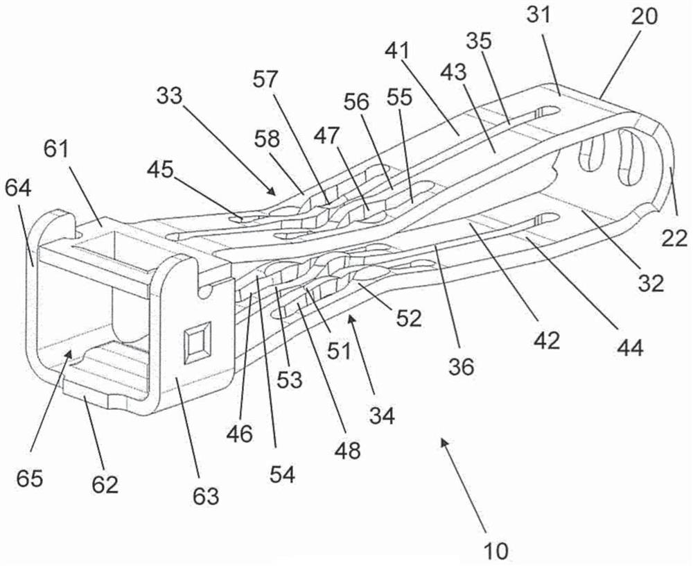
[0017] exist figure 1 A contact lug 10 of a resilient socket-type plug connection part designed according to the invention is shown in FIG. The contact lug 10 is produced in one piece from a strip-shaped sheet 20 as a stamped and bent part.

[0018] The strip-shaped sheet 20 preformed by stamping is bent in a U-shape to form the contact lug 10 , whereby the resulting U-leg forms two mutually opposite contact arms 31 , 32 . Furthermore, the contact arms 31 , 32 are not aligned parallel to each other but have a mutual distance in their longitudinal direction. In each central section 33 , 34 of their longitudinal extension, the mutual spacing of the contact arms 31 , 32 is minimal.

[0019] as in figure 1 It is further shown in , that the middle sections 33 , 34 of the contact arms 31 , 32 do not necessarily coincide with the geometric centers of the contact arms 31 , 32 . More precisely, the figures refer to the position of the sections 33 , 34 connecting the curved portion ...


PUM


Abstract

Described is a contact lug of a plug-in connection part of the plug-in type, which is made of a substantially U-shaped strip-shaped sheet, the U-side of which forms two mutually opposite contact arms , the contact arms are constructed close to each other in the middle section of their longitudinal extension, and the contact arms are each divided into two mutually parallel and adjacent contact bridges by a cutout provided on the largest part of their longitudinal extension, wherein , in the area closest to the contact arm, a contact slit is configured in the length direction of each contact bridge. Two contact strips are formed sectionally on both sides of the cutout, wherein the contact cutouts each have a transverse arc towards the center of the respective same contact arm, whereby the outer contact strip on each contact arm is aligned in the arc. Widening sections are respectively formed beside the shaped parts. In addition, a socket-type plug-in connection is described which has such a contact lug.

Description

technical field [0001] The invention relates to a contact piece of a socket-type plug-in connection part, said contact piece is formed by a substantially U-shaped strip-shaped sheet, the U-side of which forms two mutually opposite contact arms, so that The middle sections of the contact arms extending in the longitudinal direction are designed close to each other, and the contact arms are each divided into two contact bridges which are parallel to each other and adjacent to each other by means of a cut-out provided on the largest part of their longitudinal extension, wherein In the area closest to the contact arms, each contact bridge is configured in the length direction with a contact cutout which is respectively shorter than the cutout in the respective contact arm parallel thereto, so that each contact bridge is in its contact position. Two contact strips are formed in sections on both sides of the cutout. Furthermore, the invention relates to a plug-type plug connection ...

Claims


Application Information

Patent Timeline
Patent Type & Authority Patents(China)
IPC IPC(8): H01R13/187H01R13/11H01R13/24
CPCH01R13/113H01R13/187H01R13/2492H01R13/112
Inventor 沃尔夫冈·纽曼托马斯·舍雷尔
Owner KOSTAL KONTAKT SYST
Why Eureka
Try Eureka