
Pneumatic Tire

Inactive Publication Date: 2008-09-25
TOYO TIRE & RUBBER CO LTD
View PDF9 Cites 5 Cited by
  • Summary
  • Abstract
  • Description
  • Claims
  • Application Information

AI Technical Summary

Benefits of technology

[0008]The present invention is made by taking the actual condition mentioned above, and an object of the present invention is to provide a pneumatic tire which can sufficiently suppress a groove wander and can improve a rectilinear propagation stability of a vehicle.
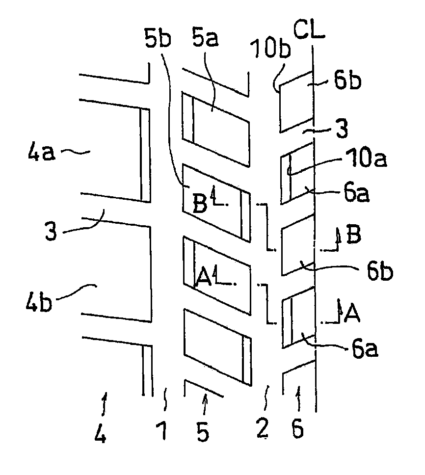
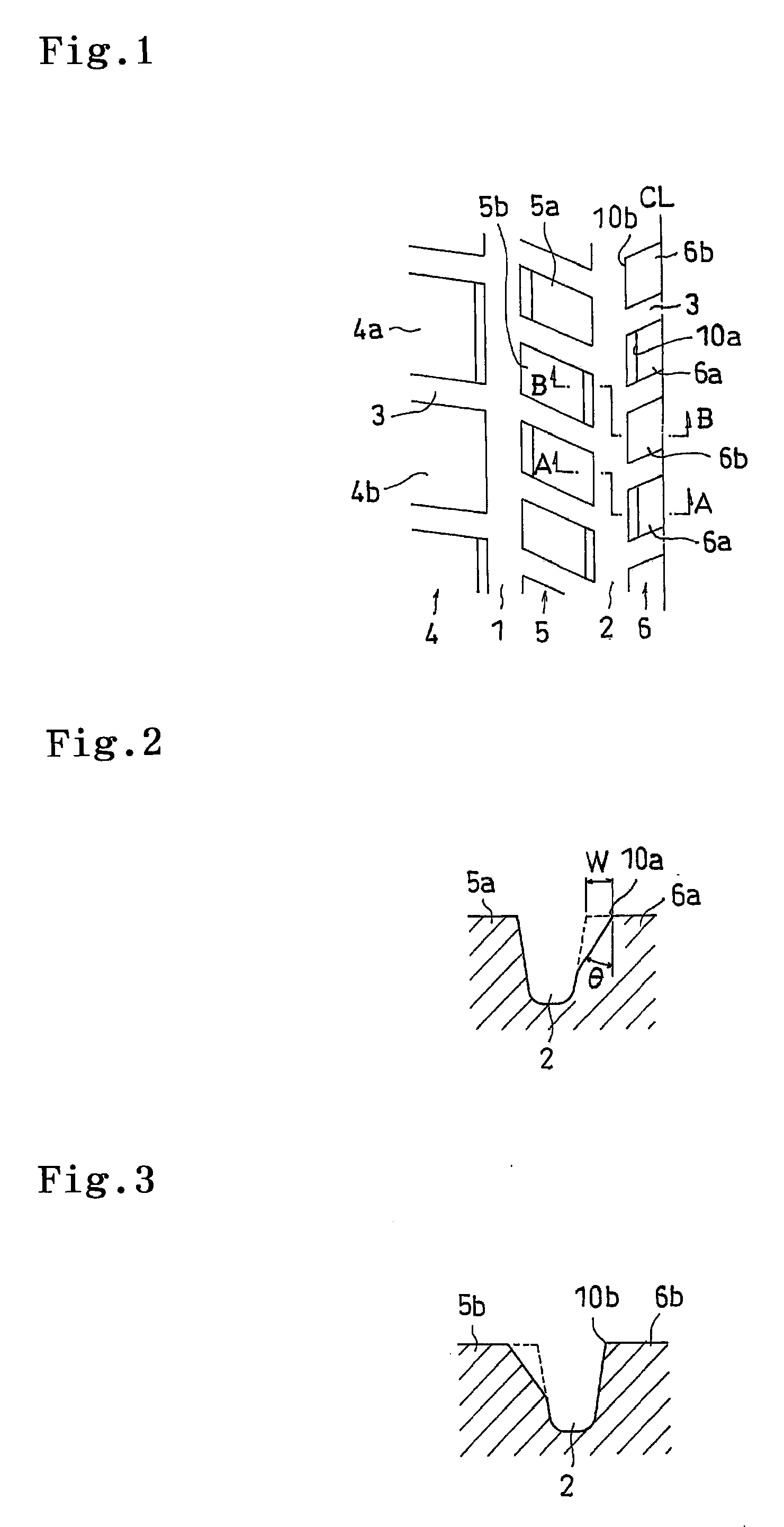
[0011]In the pneumatic tire in accordance with the present invention, since the block row has the first block and the second block as mentioned above, the position in the tire width direction of the edge portion of the wall surface facing to the main groove is not defined, but fluctuates in correspondence to the block. Accordingly, even if the edge portion of the wall surface of any one block of the first and second blocks drops within the rain groove, there is a case that the edge portion of the wall surface of the subsequent other block can be grounded on the road surface without dropping within the rain groove. Even if the edge portion of the wall surface of the other block further drops within the rain groove, it is possible to differentiate the dropping amount because the position in the tire width direction is differentiated from the edge portion which first drops. As a result, it is possible to restrict the generation of the lateral force to only a brief one so as to prevent the lateral force from being applied in a stationary manner, and it is possible to sufficiently suppress the groove wander so as to increase the rectilinear propagation stability of the vehicle.
[0013]In the above structure, it is preferable that a chamfer width of the wall surface of the first block is equal to or more than 0.6 mm, and less than 3.0 mm. In accordance with the structure mentioned above, it is possible to prevent a rigidity difference per block from becoming too large so as to suppress an irregular wear from being generated, while suitably securing the suppressing effect of the groove wander.
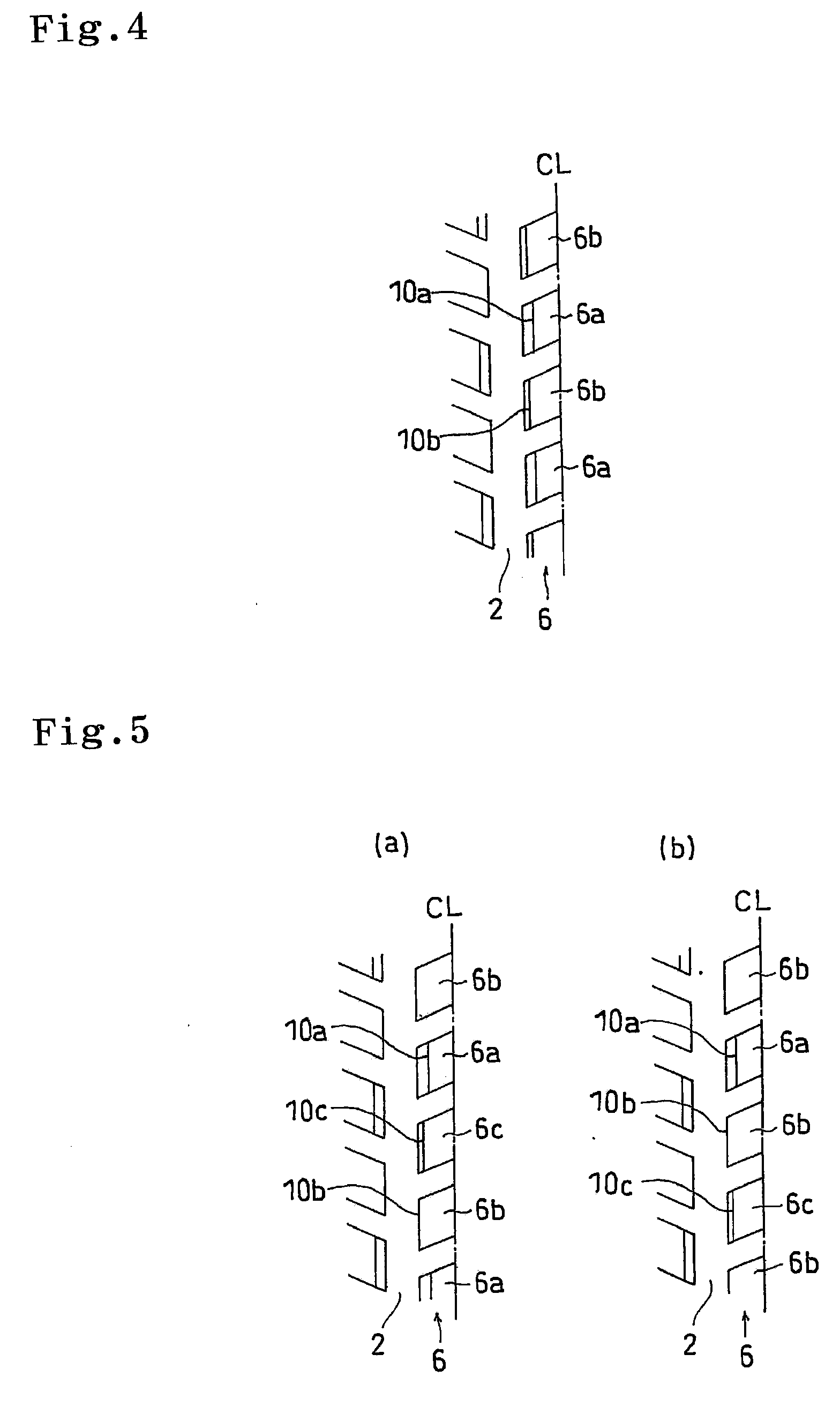
[0014]In the above structure, it is preferable that a rate of a total of circumferential lengths of the edge portions of the wall surfaces facing to the main groove of the first blocks with respect to a circumferential length of the edge portions of the wall surface facing to the main groove of the block row is between 33 and 67%. In accordance with the structure mentioned above, the first block as mentioned above is arranged suitably, a distributing balance with respect to the second block in the tire circumferential direction becomes good, and it is possible to suitably generate the operation and effect of the present invention mentioned above.
[0015]In the above structure, it is preferable that the block row is formed by alternately arranging the first blocks and the second blocks. In accordance with the structure mentioned above, since the first block and the second block as mentioned above oppose to the rain groove alternatively next to next, it is possible to restrict the generation of the lateral force to only a brief one so as to effectively prevent the lateral force from being applied in a stationary manner, and it is possible to suitably generate the operation and effect of the present invention mentioned above evenly all around the tire circumferential direction.

Problems solved by technology

Further, a reaction force caused by a collision between the drop portion and a groove wall of the rain groove RG also causes the wandering of the vehicle.
Particularly, in a vehicle having a main groove extending as a straight shape in a tire circumferential direction, since a great lateral force is applied in a stationary manner at a time when the edge portion of the wall surface of the land portion facing to the main groove drops within the rain groove, the wandering of the vehicle is significantly generated, and there is a problem that an obstacle is generated in the rectilinear propagation stability.
However, since there is a constraint on the other tire characteristics such as a drain performance or the like and a design, a freedom of design is extremely small, and there has been strongly desired to propose a method of suppressing the groove wander regardless of the pattern design.
However, in the structure mentioned above, although the wandering of the vehicle can be somewhat suppressed, since the lateral force F is applied at a time when the edge portion 30 provided by chamfering drops within the rain groove RG as shown in FIG. 8, and the vehicle wanders, it can not be the that the suppressing effect of the groove wander is sufficient, and it is necessary to further improve the effect.

Method used


Image

  • Pneumatic Tire
  • Pneumatic Tire
  • Pneumatic Tire

Examples


example

[0045]An example tire which concretely shows the structure and effect of the present invention will be explained. An evaluation of each of performances is executed as follows.

(1) Groove Wander Resistance

[0046]A tire is installed to an actual car (SUV) and is set to an air pressure 260 kPa, and a feeling evaluation on the basis of a feeling test is carried out by traveling straight on a road surface on which the rain groove is formed. A comparative example 1 is set to 100 and a result is evaluated with indices, the more the numeric value is, the more excellent the groove wander resistance is.

(2) Hydroplaning Resistance

[0047]The tire is installed to the actual car (SUV) and is set to the air pressure 260 kPa, and a speed at a time when a hydroplaning phenomenon is generated is measured by traveling on a straight course having a wet road surface of water depth 8 mm. An evaluation is shown by an index number in the case of setting a comparative example 1 to 100, and indicates that the l...


PUM


Abstract

A pneumatic tire in which a tread surface is provided with a main groove extending as a straight shape in a tire circumferential direction, and a block row formed by arranging a plurality of blocks facing to the main groove in the tire circumferential direction, the block row has a plurality of first blocks in which a wall surface facing to the main groove is chamfered, and a plurality of second blocks arranged between the first blocks and in which a position in a tire width direction of an edge portion of a wall surface facing to the main groove is differentiated from the first block.

Description

BACKGROUND OF THE INVENTION[0001]1. Field of the Invention[0002]The present invention relates to a pneumatic tire in which a tread surface is provided with a main groove extending as a straight shape in a tire circumferential direction, and a block row structured such that a plurality of blocks facing to the main groove are arranged in the tire circumferential direction.[0003]2. Description of the Related Art[0004]As one of factors affecting a rectilinear propagation stability of a vehicle, there has been known a wandering (a groove wander) caused by a rain groove. The rain groove is a groove provided for securing a traveling stability at a time of raining, and is formed on a Kyushu Vertically Passing Motor Road, a freeway in California, U.S.A. and the like. Generally, the rain groove is provided so as to be spaced at a fixed pitch in a road width direction while extending in a forward moving direction at fixed groove width and groove depth.[0005]It is known that an edge portion 20 ...

Claims


Application Information

Patent Timeline
IPC IPC(8): B60C11/13
CPCB60C11/11B60C11/1392B60C11/13
Inventor NISHITANI, KAZUMA
Owner TOYO TIRE & RUBBER CO LTD
Learn More