Optical element holding structure, optical element lens-barrel and optical communication module

a technology of optical elements and holding structures, applied in the field of optical element holding structures, optical element lensbarrels and optical communication modules, can solve the problems of internal double refraction, optical axis shifting, double refraction phenomenon, etc., and achieve the effect of controlling the deterioration of optical properties and preventing the shifting of optical axis

Inactive Publication Date: 2006-06-01
KONICA MINOLTA INC
View PDF3 Cites 26 Cited by
  • Summary
  • Abstract
  • Description
  • Claims
  • Application Information

AI Technical Summary

Benefits of technology

[0014] This invention was conceived in view of the above-described problems of the conventional and the object thereof is to provide an optical element in which it is possible to control the deterioration in optical properties even when there are changes in the environmental temperature and an optical element holding structure and a optical element lens barrel which limits the generation of internal stress in the optical element and controls the changes internal double refraction index with the optical element being held in the lens barrel even when temperature changes occur, and also which prevents shifting of the optical axis of the optical elements. An additional object of this invention is to provide an optical communication module using the optical element and optical element holding structure described above.

Problems solved by technology

However, if temperature changes occur due to the environment in which the device is used, internal stress is generated inside the plastic lens that is supported inside the lens barrel, and the internal refractive index changes due to this stress and causes the double refraction phenomenon to occur.
However, when comparing the change in stress in the optical axis direction and that on the surface perpendicular to the optical axis, the change in stress in the optical axis direction is significantly different from the change in stress on the surface perpendicular to the optical axis, causing internal double refraction.
In this optical unit, a mechanism is provided for reducing the stress on the mounting portion of the plastic lens, but this causes the optical axis to shift.
Stress inside the plastic lens is generated due to the above-described distortion, and furthermore the middle position of the lens sometimes shifts due to the method for fixing the lens inside the lens barrel.
In this manner, the signal-sending and signal-receiving properties of the transmission module are deteriorated by the environment in which the optical communication transmission module is used.

Method used


Image

  • Optical element holding structure, optical element lens-barrel and optical communication module
  • Optical element holding structure, optical element lens-barrel and optical communication module
  • Optical element holding structure, optical element lens-barrel and optical communication module

Examples


first embodiment

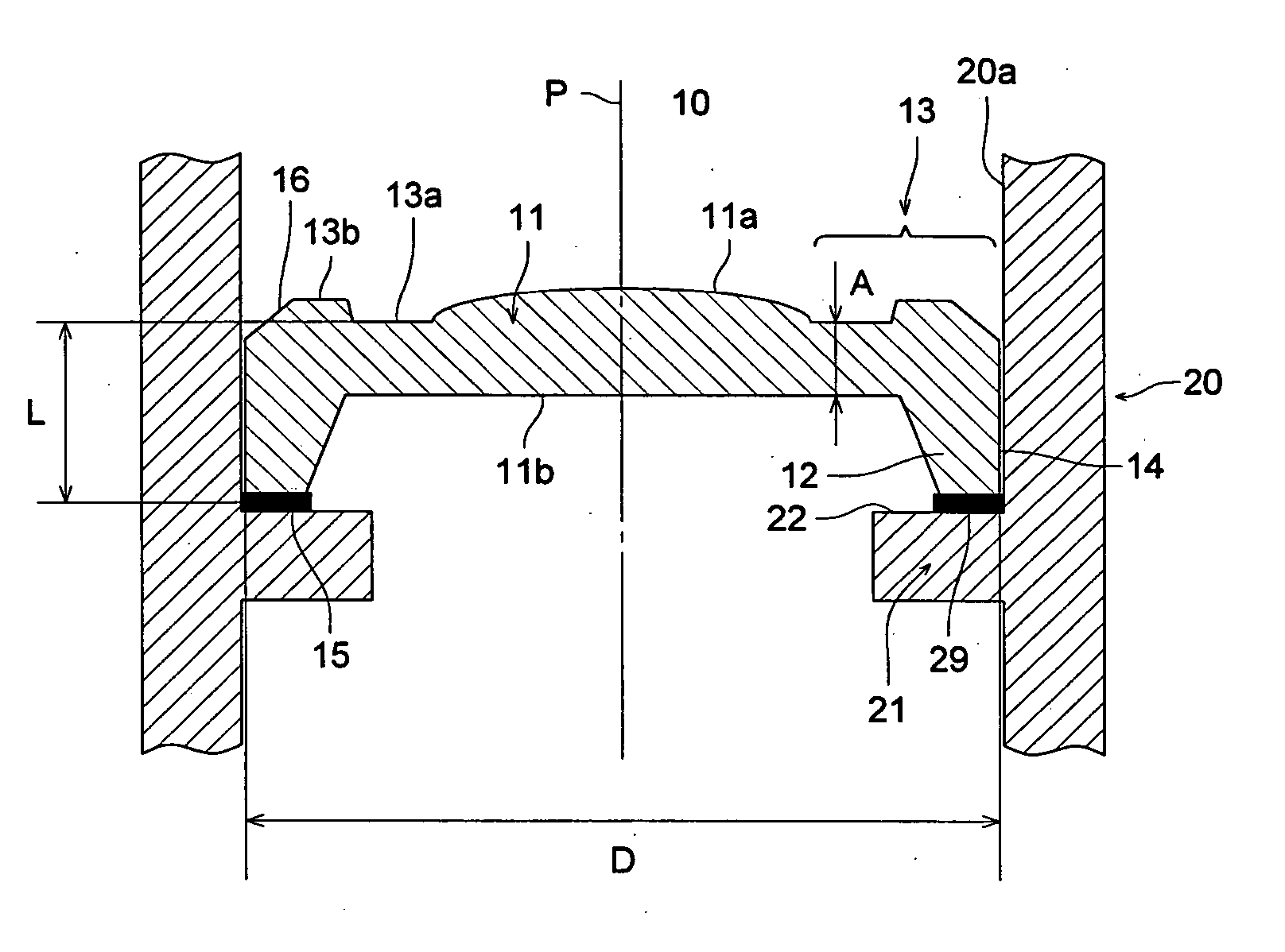
[0066]FIG. 1 is a main part vertical portion showing the lens holding structure of the first embodiment. The lens holding structure shown in FIG. 1 fixes and holds a lens 10 onto the inner surface 20a of a cylindrical lens barrel 20 using a bonding agent.

[0067] The lens 10 is made up of a lens portion 11 which has a lens function; an outer peripheral portion 13 which is positioned on the outer peripheral side of the lens portion 11 and extends to the outermost periphery 14 of the lens 10; and a mounting portion 12 which protrudes from the outer peripheral portion 13 in a direction substantially parallel to the optical axis p, and is a plastic lens which is formed from a resin for optical elements. The lens 11 has a convex portion 11a which is the center of the optical axis p, and the flat surface 11b which at the opposite side of the convex portion 11a extends from the lens portion 11 to a part of the outer peripheral portion 13. The stress reducing section is formed from the outer...

second embodiment

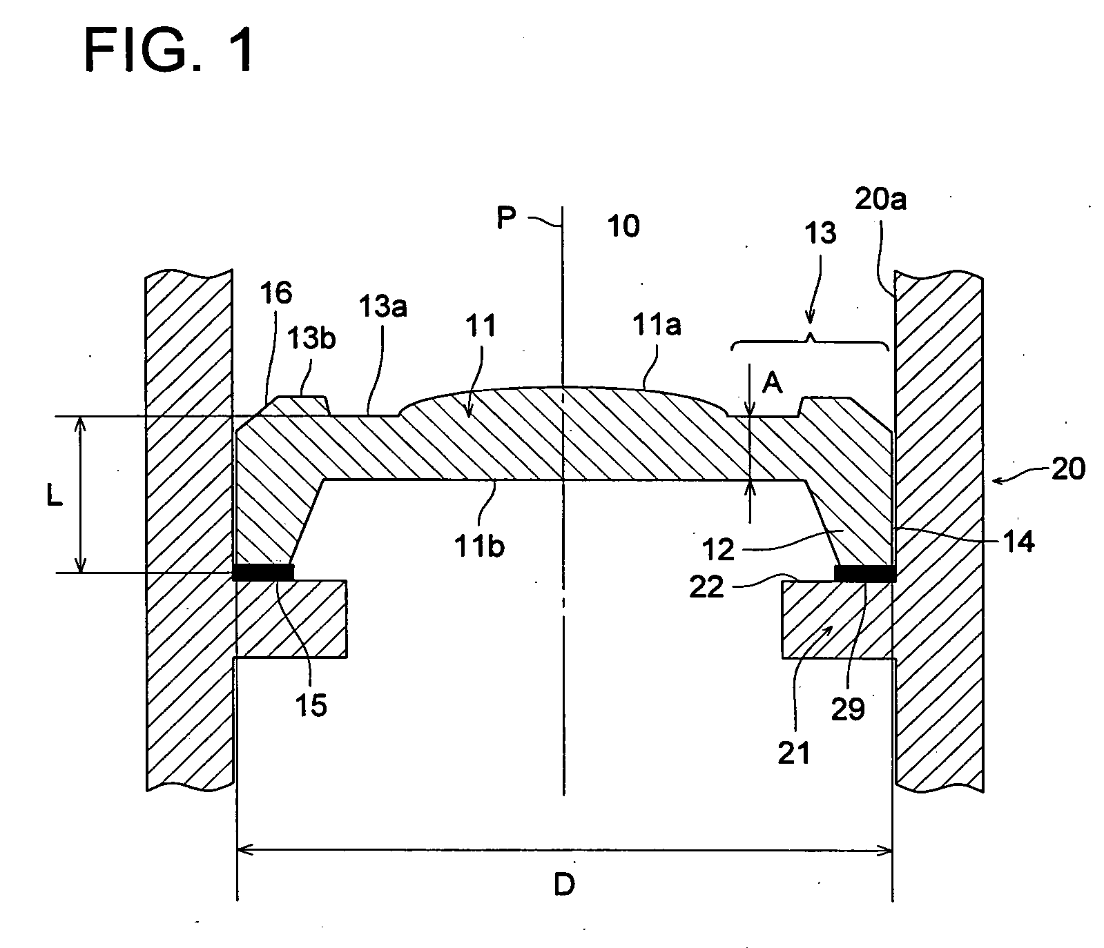
[0078]FIG. 2 is a main part vertical portion showing the lens holding structure of the second embodiment. The lens holding structure shown in FIG. 2 fixes and holds a lens 30 onto an inner surface 4.0a of a lens barrel 40 using a step structure.

[0079] As shown in FIG. 2, compared to the lens 10 of FIG. 1, the lens 30 is has substantially the same structure as that of FIG. 1 except for the fact that the mounting portion protrudes from the outer peripheral portion 13 in the direction substantially-parallel to the optical axis p has a step portion 36 which protrudes further out than the outermost periphery 14 of the lens 30 at the lower side that is opposite to the convex portion 11a of the lens portion 11. As a result, the parts that are the same have been assigned the same numbers and descriptions thereof have been omitted.

[0080] In addition the lower portion in FIG. 2 of the inner surface 40a of the lens barrel 40 is formed at an inner surface portion 41 having an inner diameter t...

third embodiment

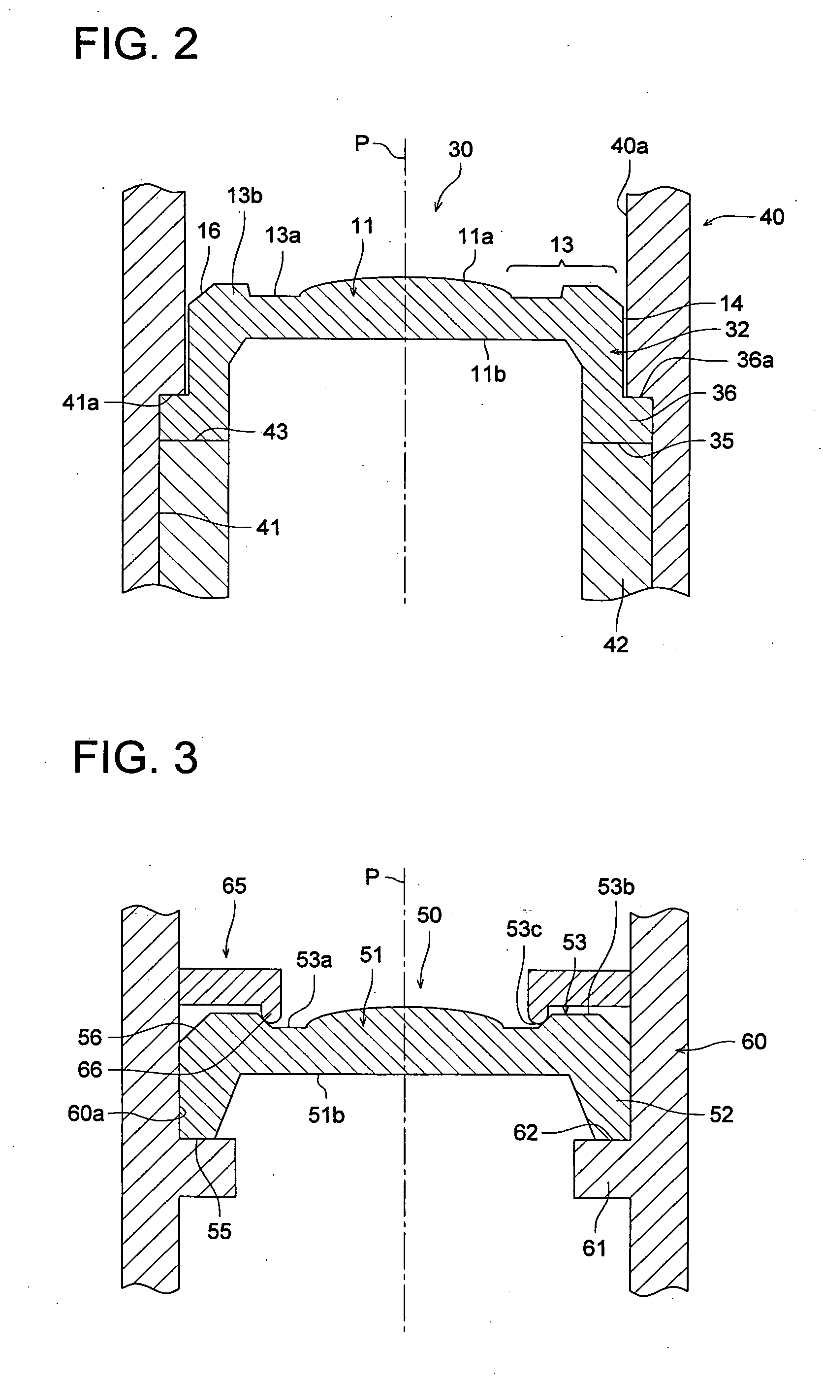
[0086]FIG. 3 is a main part vertical portion showing the lens holding structure of the third embodiment. The lens holding structure shown in FIG. 3 holds a lens 50 onto the inner surface 60a of a cylindrical lens 60 using the ring-like member 65.

[0087] The lens 50 is made up of a lens portion 51 which has a lens function; an outer peripheral portion 53 which is positioned on the outer peripheral side of the lens portion 51 and extends to the outermost periphery 54 of the lens 50; and a mounting portion 52 which protrudes from the outer peripheral portion 53 in a direction substantially parallel to the optical axis p, and is a plastic lens which is formed from a resin for optical elements. The lens 51 has a convex portion 51a which is the center of the optical axis p and a flat surface 51b which at the opposite side from the convex portion 51a extends from the lens portion 51 to a part of the outer peripheral portion 53.

[0088] The mounting portion 52 extends so as to form a leg por...


PUM


Abstract

An optical element holding structure, having: an optical element including an optical section having optical function, an outer peripheral portion which is positioned at the outer peripheral side of the optical section and a mounting portion which protrudes from the outer peripheral portion in a direction substantially parallel to the optical axis; and a lens barrel holding the optical element inside.

Description

[0001] This application claims priority from Japanese Patent Application No. 2004-343885 filed on Nov. 29, 2004 and No. 2005-073095 filed on Mar. 15, 2005, which are incorporated hereinto by reference. BACKGROUND OF THE INVENTION [0002] This invention relates to an optical element such as a lens, an optical element holding structure for holding the optical element inside a lens barrel, and to an optical-lens barrel and an optical communication module. [0003] Plastic lens are often used in optical devices in view of the fact that they have the advantage of light weight and low cost. However, if temperature changes occur due to the environment in which the device is used, internal stress is generated inside the plastic lens that is supported inside the lens barrel, and the internal refractive index changes due to this stress and causes the double refraction phenomenon to occur. The internal refractive index changes can be expressed using the following formula, but the photo-elasticity...

Claims


Application Information

Patent Timeline
Patent Type & Authority Applications(United States)
IPC IPC(8): G02B7/02
CPCG02B6/4204G02B6/4246G02B7/022G02B7/028
Inventor SHIBUYA, YOSHIKIFURUTA, KAZUMIMIYAKOSHI, HIROSHIHORII, KOJI
Owner KONICA MINOLTA INC
Why Eureka
Try Eureka