Valve spring device and valve train of engine using the same

a valve spring and valve train technology, applied in the direction of spring/damper functional characteristics, machines/engines, mechanical apparatus, etc., can solve the problems of large inertia force and bulky upper parts of engines, and achieve the effect of suppressing the occurrence of surg

Active Publication Date: 2010-06-10
NHK SPRING CO LTD
View PDF0 Cites 5 Cited by
  • Summary
  • Abstract
  • Description
  • Claims
  • Application Information

AI Technical Summary

Benefits of technology

[0011]In the valve spring device described in Jpn. Pat. Appln. KOKAI Publication No. 2000-240705, the two types of springs (compression coil spring and elastically deformable washer) are arranged in series with each other, so that the axial length (set height) of the device is substantial. Thus, a great force of inertia is generated when the engine is turning fast, for example, so that various problems arise. Since the valve train is thus increased in size, moreover, the upper part of the engine becomes bulkier.
[0012]Accordingly, the object of the present invention is to provide a valve spring device, capable of suppressing surge and reducing an axial dimension, and a valve train of an engine using the same.
[0014]According to the present invention, the first and second coil springs with different spring characteristics are combined in series with each other, so that the occurrence of surge can be suppressed. Since the two types of coil springs are arranged telescopically, moreover, the total axial length (set height) can be prevented from increasing, so that the force of inertia of the valve train that reciprocates at high speed can be reduced. The first and second coil springs are separate from each other. Thus, a desired valve spring device can be obtained by suitably selecting and combining the first and second coil springs that have different spring characteristics, depending on the surge resistance, set height, etc., required of the valve spring device.

Problems solved by technology

Thus, a great force of inertia is generated when the engine is turning fast, for example, so that various problems arise.
Since the valve train is thus increased in size, moreover, the upper part of the engine becomes bulkier.

Method used


Image

  • Valve spring device and valve train of engine using the same
  • Valve spring device and valve train of engine using the same
  • Valve spring device and valve train of engine using the same

Examples


Embodiment Construction

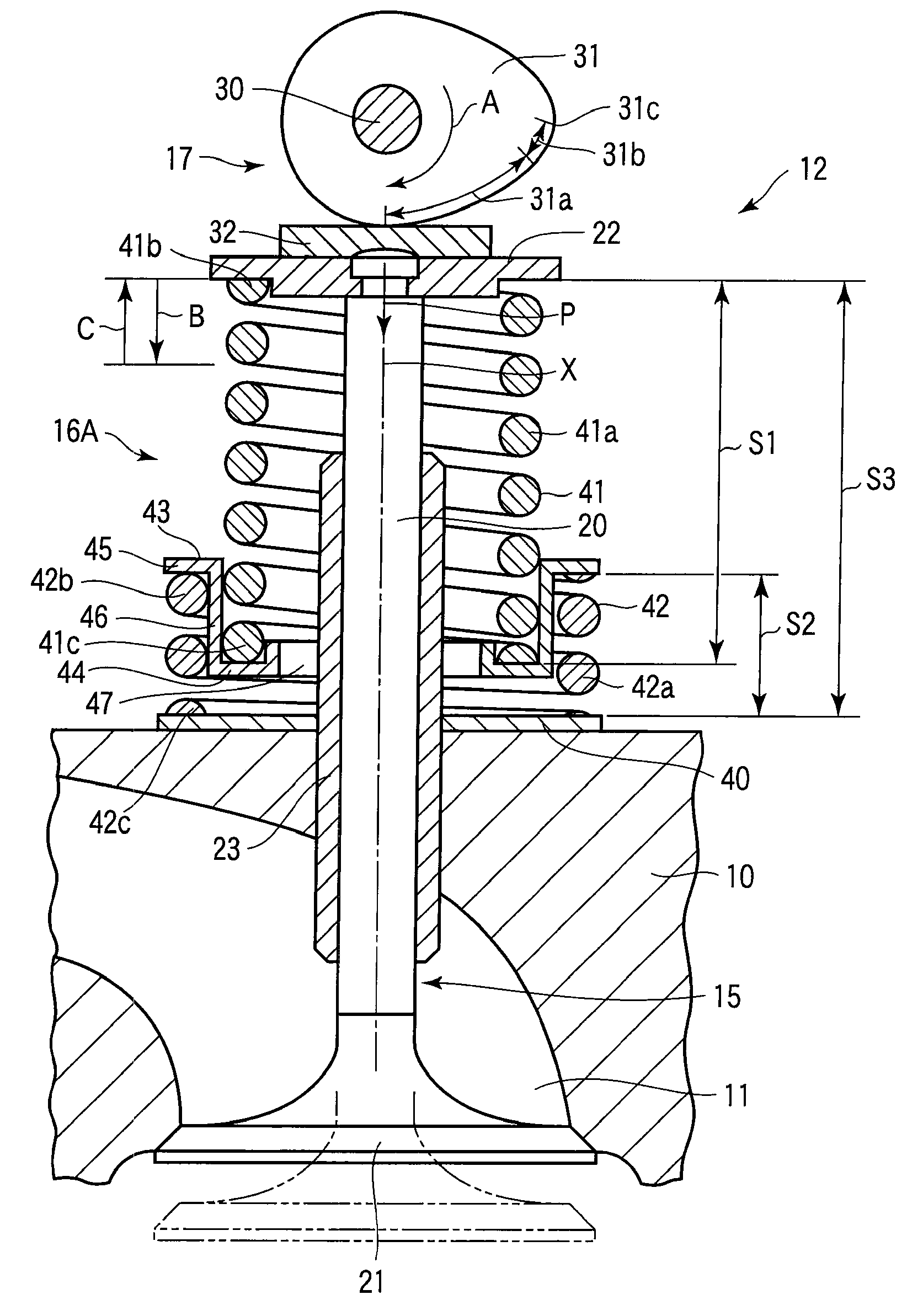
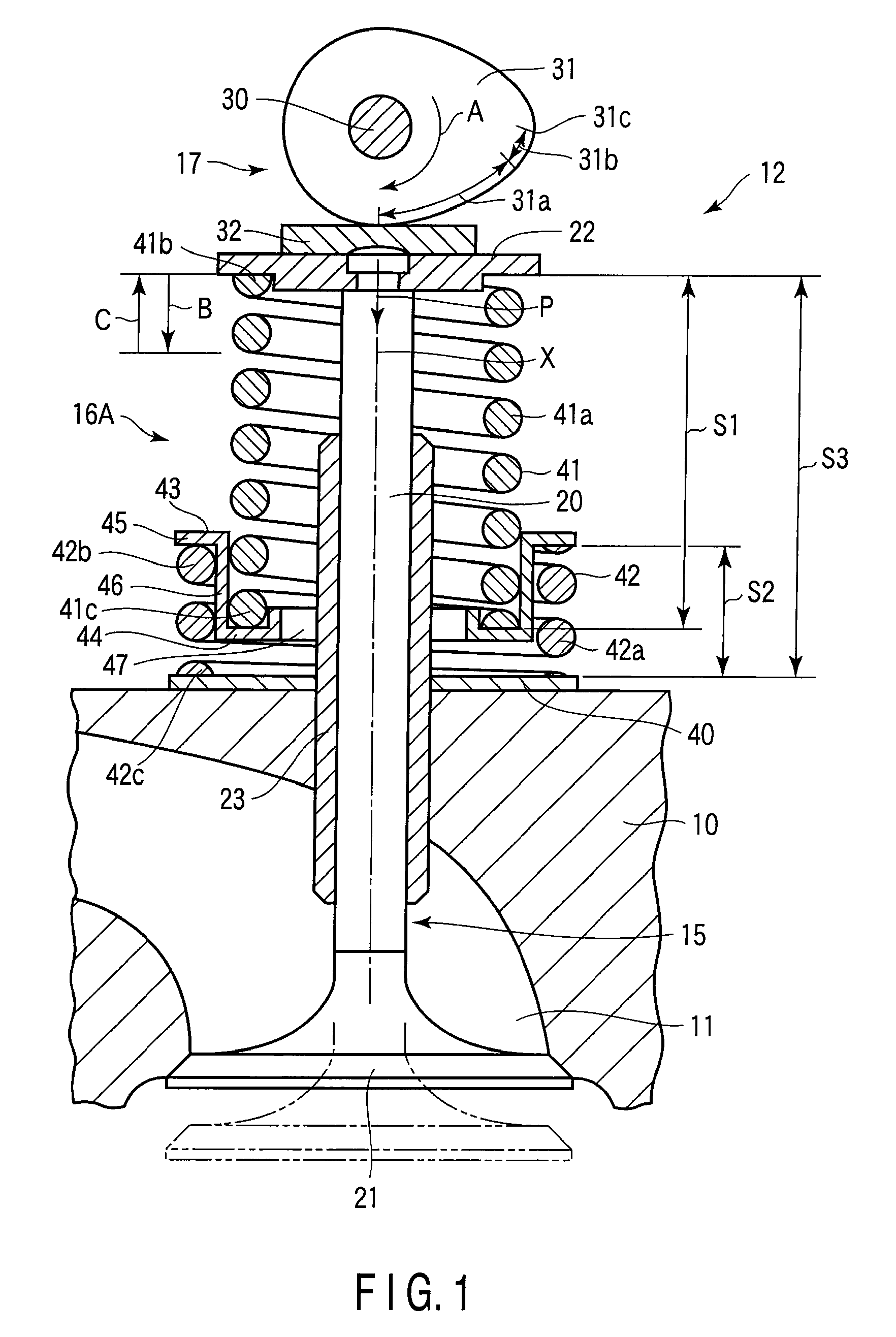
[0023]A valve spring device according to a first embodiment of the present invention will now be described with reference to FIG. 1. As shown in FIG. 1, an intake port 11 is formed in a cylinder head 10 of an engine. The cylinder head 10 is provided with an intake valve train 12. The valve train 12 includes an intake valve 15, a valve spring device 16A, a drive mechanism 17, etc. The valve 15 opens and closes the intake port 11. The valve spring device 16A urges the valve 15 in its closing direction. The drive mechanism 17 drives the valve 15 in its opening direction.

[0024]The cylinder head 10 is provided with an exhaust port (not shown) and an exhaust valve train (not shown) for opening and closing the exhaust port. Since the exhaust valve train is constructed substantially in the same manner as the intake valve train 12, a description thereof is omitted herein, and the intake valve train 12 will now be described as a representative.

[0025]The valve 15 that is incorporated in the in...


PUM


Abstract

A valve spring device is provided with a first coil spring and a second coil spring combined in series with each other. The inside diameter (coil inside diameter) of the second coil spring is greater than the outside diameter (coil outside diameter) of the first coil spring. A part of the first coil spring including an end portion along an axis is inserted into the second coil spring, thereby forming a combined spring. The end portion of the first coil spring and an end portion of the second coil spring are connected to each other by a connecting member. The first and second coil springs are compressed along the axis as they are located in series between a cylinder head and a retainer. A shaft of a valve is passed within the coil springs.

Description

CROSS REFERENCE TO RELATED APPLICATIONS[0001]This is a Continuation application of PCT Application No. PCT / JP2008 / 064134, filed Aug. 6, 2008, which was published under PCT Article 21(2) in Japanese.[0002]This application is based upon and claims the benefit of priority from prior Japanese Patent Application No. 2007-211896, filed Aug. 15, 2007, the entire contents of which are incorporated herein by reference.BACKGROUND OF THE INVENTION[0003]1. Field of the Invention[0004]The present invention relates to a valve spring device incorporated in an engine of, for example, an automobile and a valve train using the valve spring device.[0005]2. Description of the Related Art[0006]A valve train of an internal combustion engine (hereinafter referred to simply as the engine) includes an intake valve, an exhaust valve, a valve spring, a drive mechanism, etc. The valves serve individually to open and close ports in the cylinder head. The valve spring urges these valves in their closing directio...

Claims


Application Information

Patent Timeline
Patent Type & Authority Applications(United States)
IPC IPC(8): F01L3/10
CPCF01L1/205F01L1/462F16F2228/08F16F3/04F01L3/10
Inventor IWATA, KAZUOTAKAMURA, NORITOSHITOMINAGA, JUNTAJIMA, NORIHIRO
Owner NHK SPRING CO LTD
Why Eureka
Try Eureka