Bearing seal and mold assembly for forming such bearing seal

a technology of bearing seals and molds, applied in the field of bearing seals, can solve the problems of high manufacturing cost and extremely poor workability, and achieve the effects of reducing production costs, increasing the coupling force of rubber seals to metal cores, and increasing rigidity of rubber seals

Active Publication Date: 2013-02-12
NTN CORP +1
View PDF6 Cites 0 Cited by
  • Summary
  • Abstract
  • Description
  • Claims
  • Application Information

AI Technical Summary

Benefits of technology

[0014]An annular groove is preferably formed in the radially inner surface of the small-diameter thick-walled portion to extend along the outer surface of the outer lip. With this arrangement, the outer lip has a radial length that is substantially equal to the radial lengths of the other two lips, so that the contact pressures of the respective lips against the inner race pressure are also substantially equal to each other. This prevents the outer lip from becoming worn to a higher degree than the other lips due to contact with the inner race.
[0015]Preferably, the difference in radius between the inner diameter of the radially inner flange and the inner diameter of the annular groove is set to be 0.1 mm or over and 1.0 mm or under, or the difference in radius between the inner diameter of the annular groove and the inner diameter of the small-diameter thick-walled portion is set to be 0.1 mm or over and 1.0 mm or under, and further the axial length of the small-diameter thick-walled portion from its outer end surface to the annular groove is set to be larger than the thickness of any of the three lips. With this arrangement, the rigidity of the rubber seal increases. Also, when releasing the upper mold, the small-diameter thick-walled portion engages the annular portion of the lower mold, thus preventing separation of the finished product. This makes it possible to reliably leave the finished product in the lower mold.
[0016]With the bearing seal according to the present invention, since the thick-walled portion includes a cylindrical small-diameter thick-walled portion extending axially outwardly from an outermost one of the three lips and covering a radially inner surface of the radially inner flange, and the rubber seal further includes a thin-walled outer surface covering portion connected to the small-diameter thick-walled portion and covering the outer surface of the radially inner flange, the rigidity of the rubber seal increases, and the coupling force of the rubber seal to the metal core increases. This makes it possible to form the bearing seal using a two-piece mold assembly comprising a lower mold and an upper mold, thus reducing the production cost.
[0017]With the bearing seal mounted in a bearing, the tips of the three lips are elastically in contact with the cylindrical radially outer surface of the inner race. Thus, this bearing seal shows extremely high grease sealability, dust-proof properties and waterproofness as with conventional bearing seals. Further, the small-diameter thick-walled portion, which covers the radially inner surface of the radially inner flange, prevents foreign objects having large diameters such as sand from colliding against the outer lip. This improves durability of the lips.

Problems solved by technology

With this three-piece mold assembly, as in the case with an ordinary two-piece mold assembly comprising a lower mold and an upper mold, it is impossible to leave the finished bearing seal in the lower mold A, workability is extremely poor and the manufacturing cost is high.

Method used


Image

  • Bearing seal and mold assembly for forming such bearing seal
  • Bearing seal and mold assembly for forming such bearing seal
  • Bearing seal and mold assembly for forming such bearing seal

Examples


Embodiment Construction

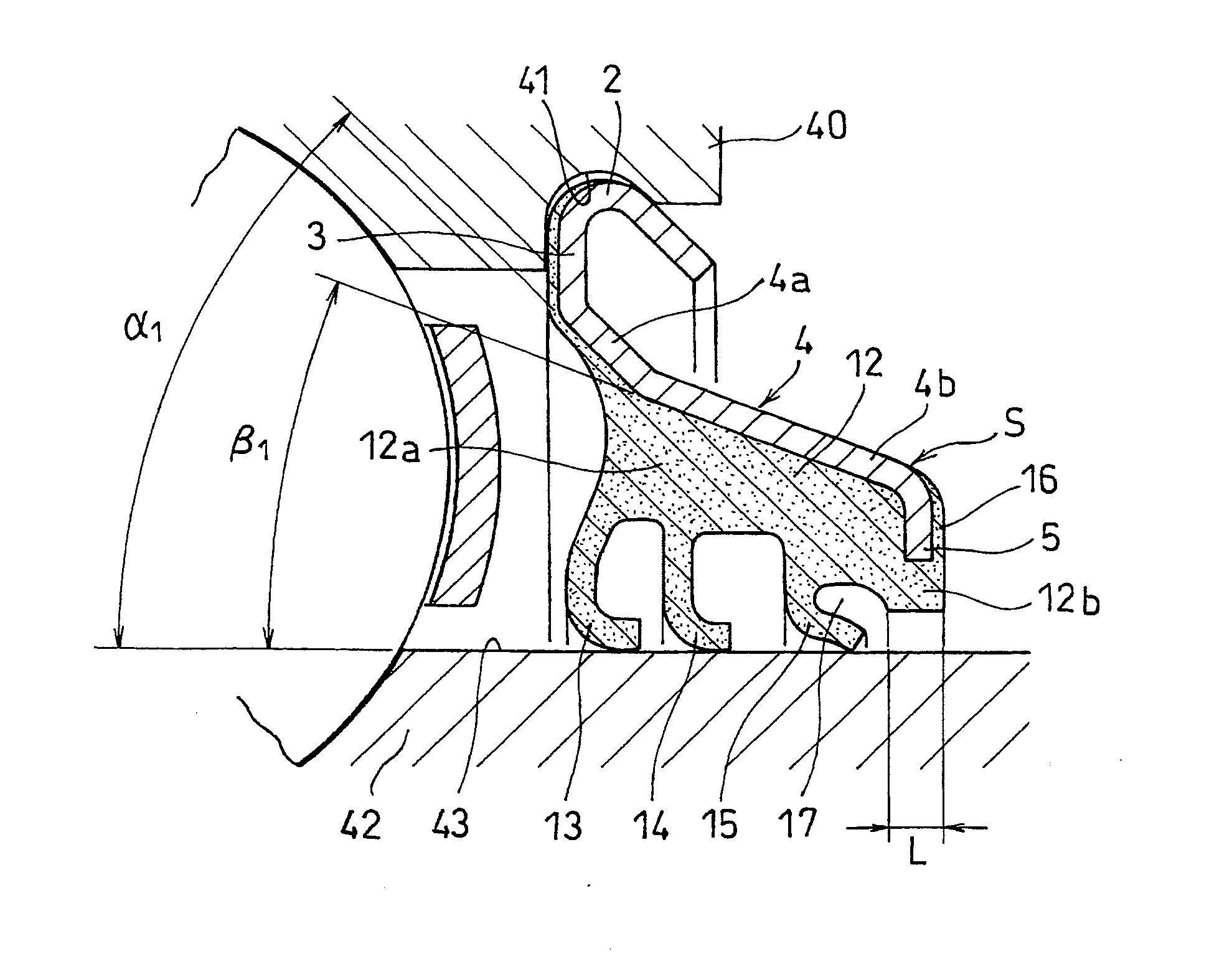
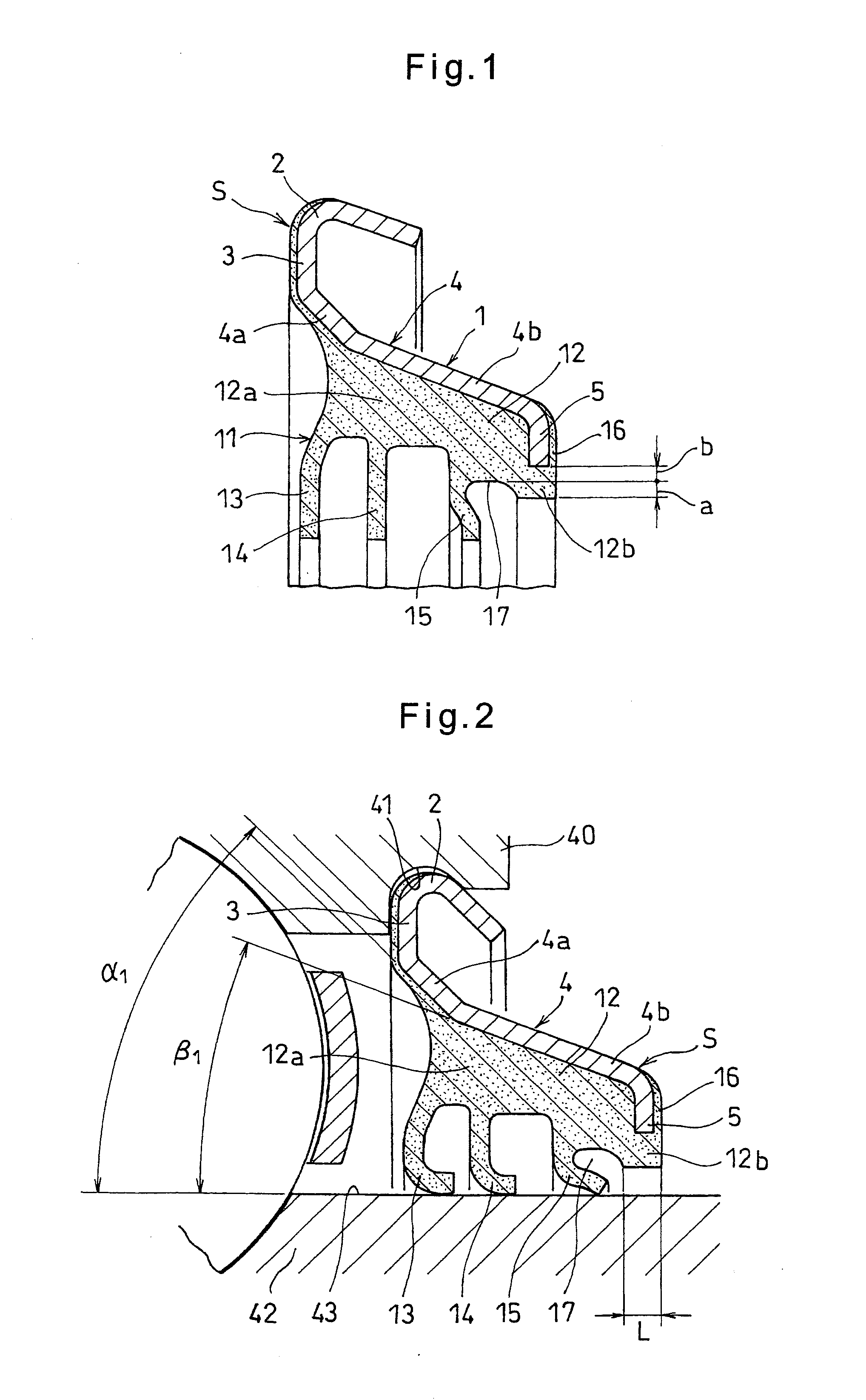
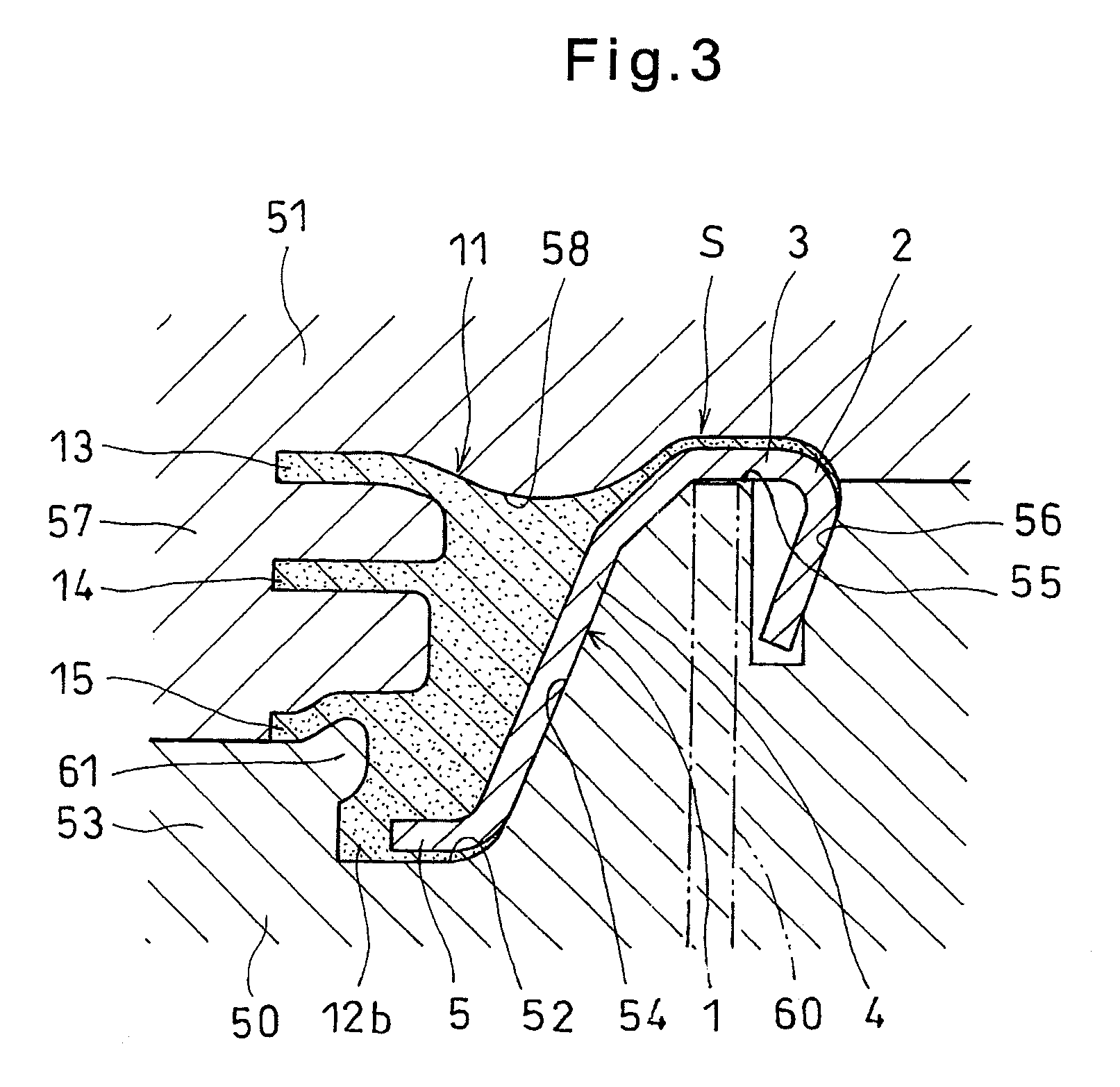
[0037]Now the embodiment of the present invention is described with reference to FIGS. 1 to 3. As shown in FIG. 1, the bearing seal S embodying the present invention comprises a metal core 1 and a rubber seal 11 fixed to the metal core 1.

[0038]The metal core 1 is formed by pressing a thin steel sheet. The metal core 1 comprises a bent portion 2 press-fitted in a seal groove 41 formed in the radially inner surface of an outer race 40 of a bearing shown in FIG. 2 at its end portion, a radially outer flange 3 extending radially inwardly from the end of the bent portion 2 located inside of the bearing, a tapered tubular portion 4 having its large-diameter end connected to the small-diameter end of the radially outer flange 3 and its small-diameter end located axially outwardly of its large-diameter end, and a radially inner flange 5 extending radially inwardly from the small-diameter end of the tapered tubular portion 4.

[0039]The tapered tubular portion 4 comprises a large-diameter tape...


PUM

PropertyMeasurementUnit
inner diameteraaaaaaaaaa
diameteraaaaaaaaaa

Abstract

A bearing seal includes a metal core having a radially outer portion engaged in an inner seal groove of a bearing outer race. The core includes a bent portion engaged in the seal groove, a radially outer flange extending inwardly from an end of the bent portion located inside the bearing, a tapered tubular portion having a large-diameter end thereof connected to a small-diameter end of the outer flange and a small-diameter end thereof located axially outwardly of its large-diameter end, and a radially inner flange extending inwardly from the small-diameter end of the tubular portion. A rubber seal is fixed to an inner surface of the metal core that faces the interior of the bearing. The rubber seal includes a thick-walled portion having an inner radial step, and formed with three lips that elastically contact the inner race outer surface. The thick-walled portion includes a small-diameter thick-walled portion.

Description

TECHNICAL FIELD[0001]This invention relates to a bearing seal for sealing the bearing space of a rolling bearing, and a mold assembly for forming such a bearing seal.BACKGROUND ART[0002]FIG. 4(I) shows a known bearing seal for sealing the bearing space of a rolling bearing. This bearing seal comprises a metal core 21 and a rubber seal 31 fixed to the metal core 21.[0003]The metal core 21 comprises a bent portion 22 press-fitted in a seal groove 41 formed in the radially inner surface of an outer race 40 of a bearing at each end portion thereof, a radially outer flange 23 extending radially inwardly from the end of the bent portion 22 located inside of the bearing, a tapered tubular portion 24 having its large-diameter end connected to the small-diameter end of the radially outer flange 23 and its small-diameter end located axially outwardly of its large-diameter end, and a radially inner flange 25 extending radially inwardly from the small-diameter end of the tapered tubular portion...

Claims


Application Information

Patent Timeline
Patent Type & Authority Patents(United States)
IPC IPC(8): F16J15/32F16J15/3232F16C33/78
CPCF16J15/3232F16C33/7853
Inventor OKAJI, YOSHITAKAURAKAMI, EIICHI
Owner NTN CORP
Why Eureka
Try Eureka