
Safety syringe

a safety syringe and syringe technology, applied in the field of safety syringes, can solve the problems of increasing the risk of accidental infections of medical personnel, troublesome assembly of medical personnel, and the chance of medical personnel directly touching the needle with their hands, so as to increase the convenience of use, facilitate assembly, and improve the effect of convenien

Inactive Publication Date: 2021-10-28
HUNG CHIH HUA
View PDF0 Cites 0 Cited by
  • Summary
  • Abstract
  • Description
  • Claims
  • Application Information

AI Technical Summary

Benefits of technology

The present invention is a safety syringe that has a simple structure and easy assembly to increase its use convenience. The main technical effect of the invention is to limit the range of movement of the inner barrel within the outer barrel, which prevents accidental collisions during injection and ensures safety after injection. The inner barrel is positioned within the outer barrel to keep the needle and needle mount inside, which also makes the attachment of the needle easier and safer due to the limited movement of the inner barrel. The design of the outer barrel allows for easy assembly of the syringe and ensures the needle and needle mount are always in the correct position. This reduces the force required to move the inner barrel, making the syringe easier to use.

Problems solved by technology

The early safe handling method was to insert the used needle into a needle cover for storage, but during the insertion process, the hands of the medical personnel may be accidentally pierced by the needle due to their carelessness or being pushed by other external forces, which in turn increases the risk of accidental infections for the medical personnel.
Such problems also lead to so-called safety syringes to reduce the chance of medical personnel directly touching the needle with their hands.
However, in the aforementioned prior art, the medical personnel needs to apply a large thrust to the plunger in order to form a snap connection between the plunger and the needle holder.
This will not only cause medical personnel's assembly trouble, but if the force is too large, it may cause structural damage.

Method used


Image

  • Safety syringe
  • Safety syringe
  • Safety syringe

Examples


Embodiment Construction

[0023]The following describes the technical content and features of the present invention in detail with the enumerated several preferred embodiments and the drawings. The directional adjectives of “front”, “rear”, “inside”, “outside” and the like mentioned in the description of this specification are merely examples of descriptions based on the direction of normal use and are not intended to limit the scope of claims.

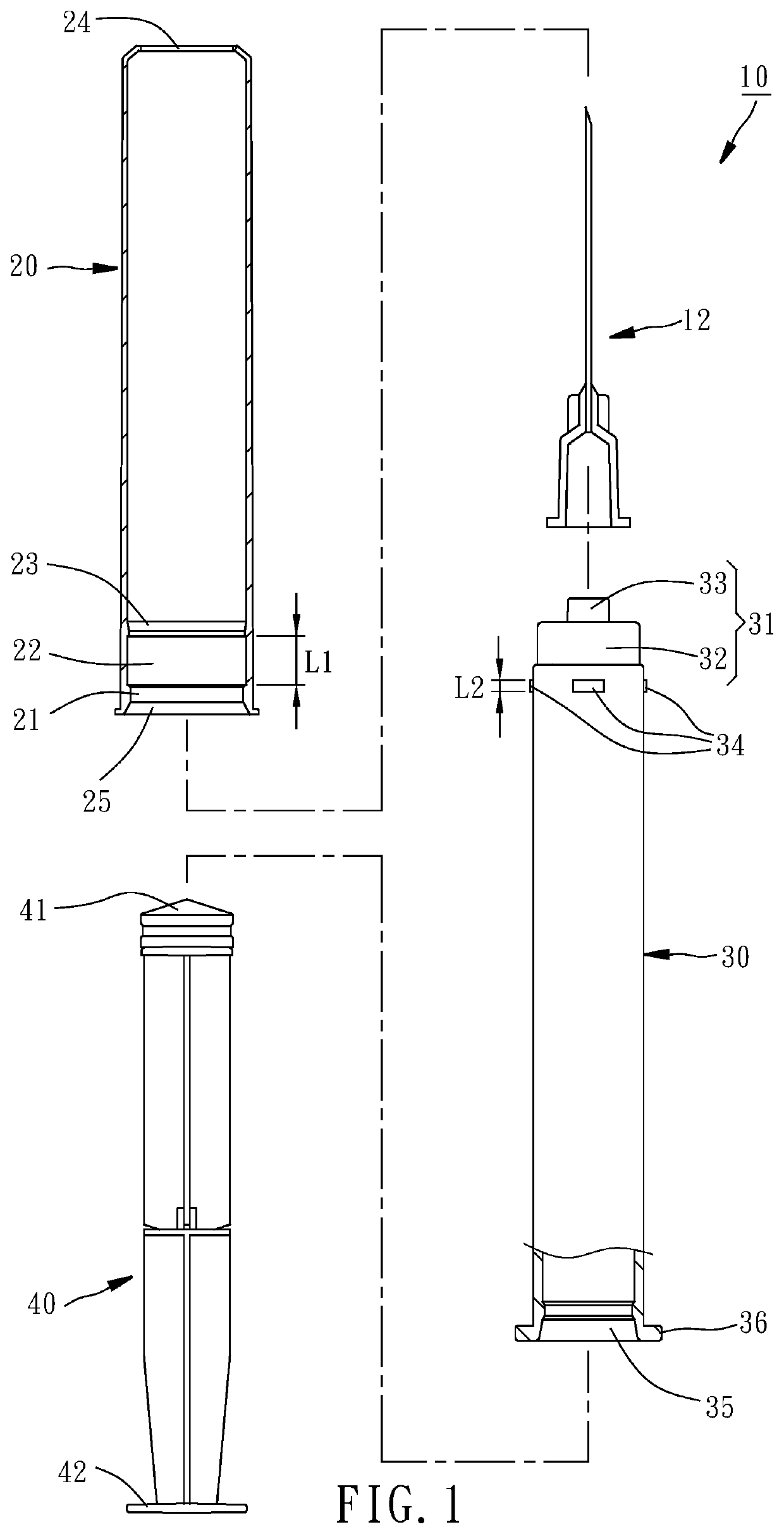
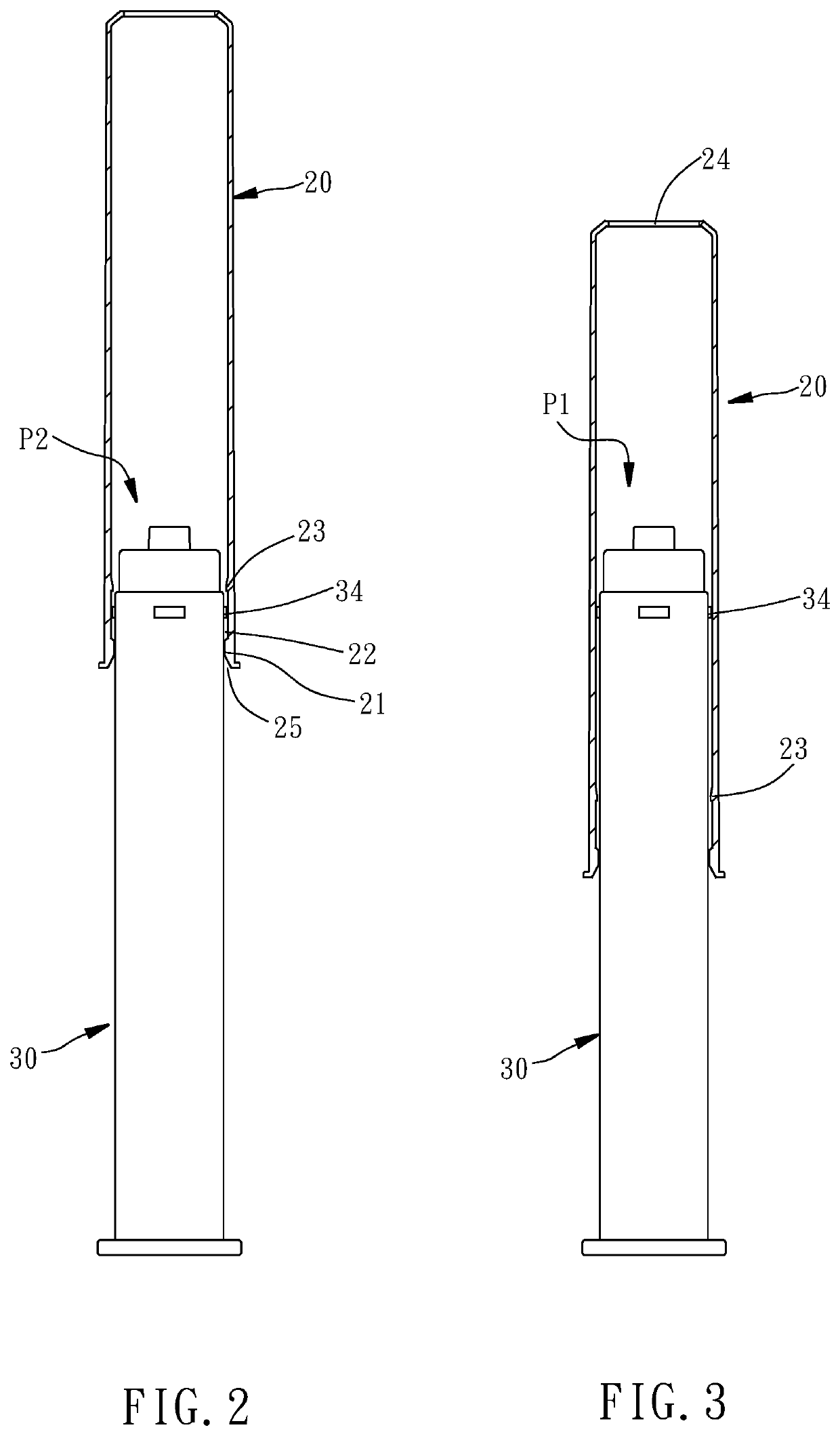
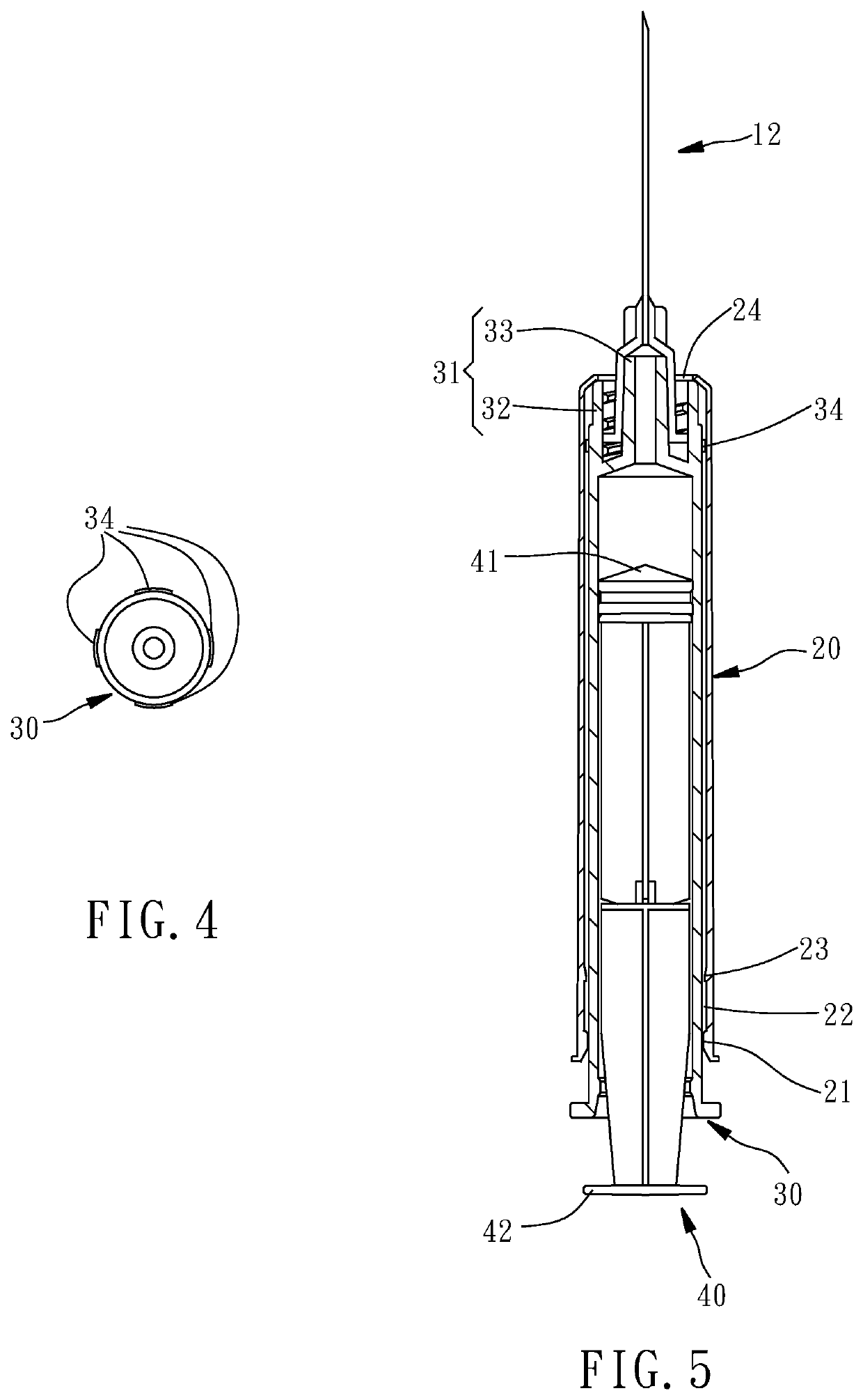
[0024]Referring to FIG. 1, a safety syringe 10 in accordance with a first embodiment of the present invention comprises an outer barrel 20, an inner barrel 30, and a plunger 40.

[0025]The outer barrel 20 is made of plastic. In order from back to front, the inner wall surface of the rear end of the outer barrel 20 has a first annular flange 21, a receiving groove 22 adjacent to the first annular flange 21, and a second annular flange 23 adjacent to the receiving groove 22. The second annular flange 23 gradually increases in the inner diameter in direction away from the r...


PUM


Abstract

A safety syringe includes an outer barrel having a receiving groove located on an inner surface of a rear end thereof between a first annular flange and a second annular flange, an inner barrel having a needle mount located on a front end thereof and a positioning portion adjacent to the needle mount, and a plunger axially movably inserted into the inside of the inner barrel.

Description

BACKGROUND OF THE INVENTION1. Field of the Invention[0001]The present invention relates to safety syringes and more particularly, to such a safety syringe that has a simple structure and is easy to assemble.2. Description of the Related Art[0002]A syringe is a device to be used with a needle for injecting liquids such as medical fluid, blood or nutritional fluid into the human body. After the injection is completed, the needle is already contaminated with human blood, so the used needle must be safely processed to avoid medical staff or other people being injured by the needle. The early safe handling method was to insert the used needle into a needle cover for storage, but during the insertion process, the hands of the medical personnel may be accidentally pierced by the needle due to their carelessness or being pushed by other external forces, which in turn increases the risk of accidental infections for the medical personnel. Such problems also lead to so-called safety syringes t...

Claims


Application Information

Patent Timeline
IPC IPC(8): A61M5/315A61M5/31A61M5/19
CPCA61M5/31505A61M5/3134A61M2005/31506A61M5/19A61M2005/3131A61M5/3158A61B5/15003A61B5/150641A61B5/150916A61B5/153A61M5/281A61M5/3245A61M5/3275A61M5/5086A61M2005/3247A61M2005/3249A61M2205/0216A61M2205/273A61M5/50
Inventor HUNG, CHIH-HUA
Owner HUNG CHIH HUA
Learn More