Recoil starter

a starter and reel technology, applied in the direction of engine starters, muscle operated starters, machines/engines, etc., can solve the problems of not supporting the rope reel and not stably providing the shaft portion

Active Publication Date: 2010-08-10
STARTING IND CO LTD
View PDF4 Cites 1 Cited by
  • Summary
  • Abstract
  • Description
  • Claims
  • Application Information

AI Technical Summary

Benefits of technology

[0009]The present invention resolves these shortcomings, and one objective of the invention is to provide a recoil starter that can reduce the operating load imposed on a rope reel, and that can ensure a steady smooth operation.
[0013]According to such a configuration, a bearing is mounted on a partition wall that closes a side opening in an engine crankcase, and a clutch mechanism is provided on the crankcase end of a rotary shaft that passes through the bearing, while a rope reel is provided on the opposite end of the rotary shaft and a damper spring is positioned outside the rope reel. Since the clutch mechanism on which a load is imposed during transferring a rotational force to the engine and the rope reel on which a load is imposed by the withdrawal of the recoil rope are positioned at either end of the bearing, the effective load on the bearing can be reduced, and a steady, smooth operation can be obtained. In addition, a special strength is not required for the starter case that covers the recoil starter.
[0015]According to such a configuration, since a recoil spiral spring is located between the partition wall and the rope reel, after the recoil rope has been pulled out to start the engine, the rope is automatically rewound on the rope reel by the recoil spiral spring, and the damper spring having a larger axial length as compared with the recoil spring is disposed on the opposite side of the rope reel. This arrangement permits the rope reel to be positioned nearer the bearing.

Problems solved by technology

Since the shaft portion is formed short, the shaft can not support the rope reel and the cam member along the entire lengths, and merely holds them along only one side.
Further, while the starter case is secured to the crankcase of the engine, the shaft portion is not stably provided because it is located away from the crankcase.

Method used


Image

  • Recoil starter
  • Recoil starter
  • Recoil starter

Examples


Embodiment Construction

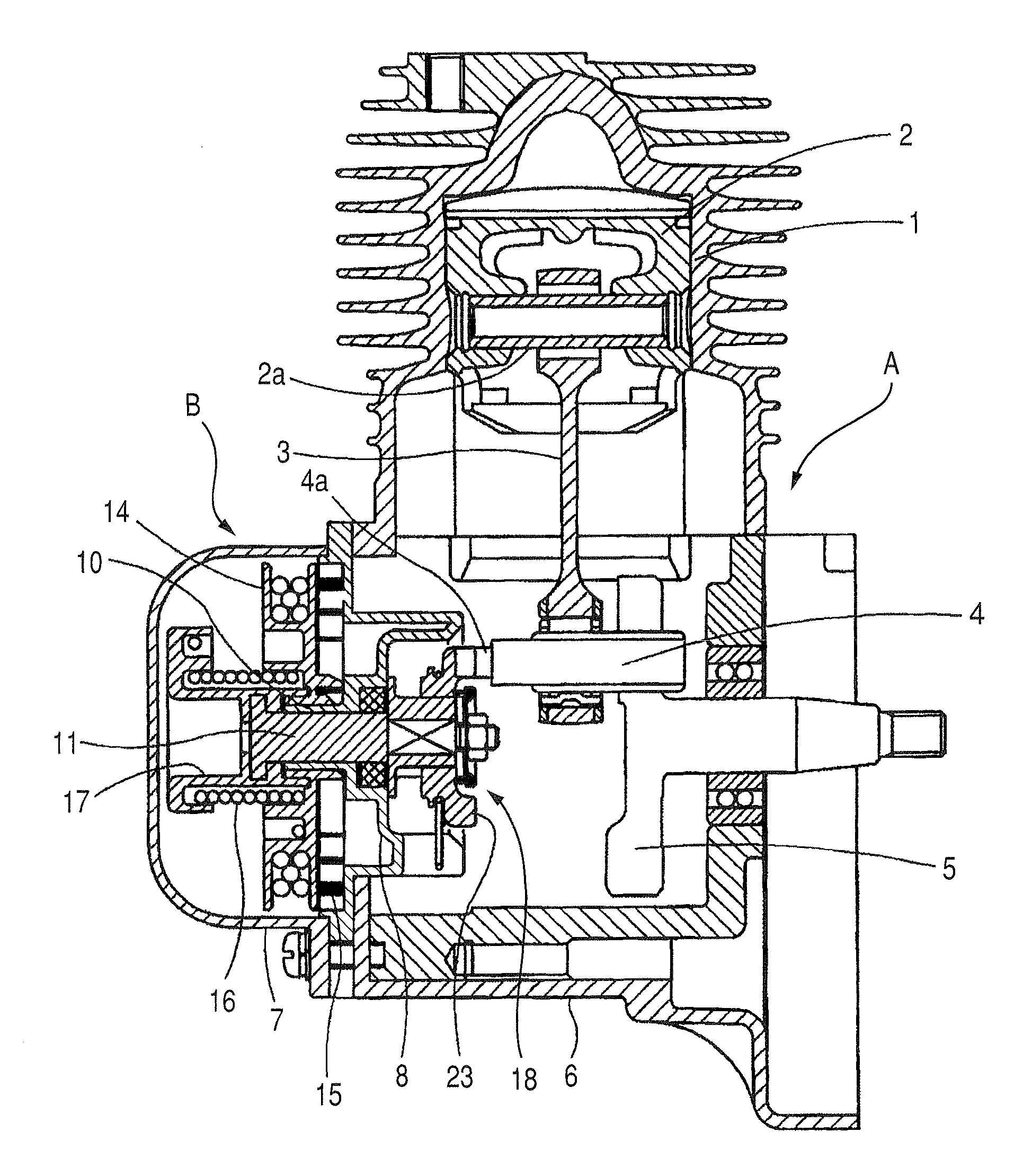
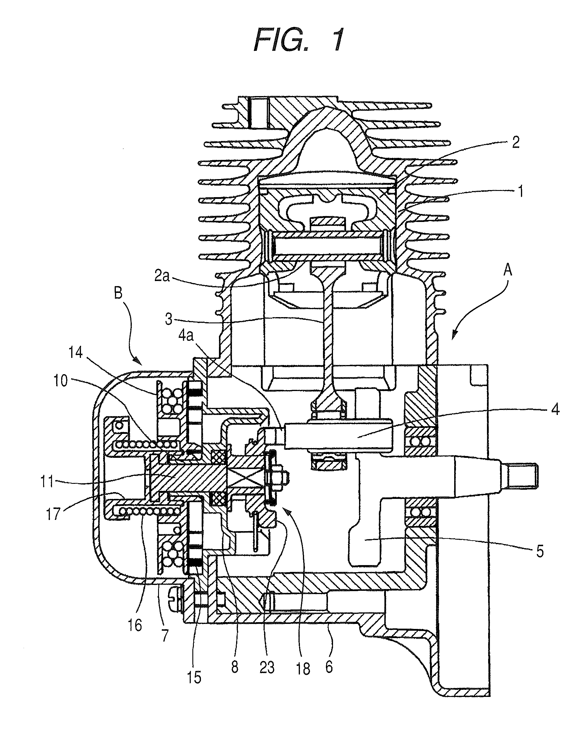
[0021]An engine A is shown in FIG. 1. In the engine A, a cylinder 1 that accommodates a piston 2 so that the piston 2 is freely reciprocatable within the cylinder 1 is provided. The piston 2 is connected to one end of a connecting rod 3 via a piston pin 2a. The other end of the connecting rod 2 is connected to a crankshaft 4 that is arranged within a crankcase 6. In the crankcase 6, a flywheel 5 is provided. The crankshaft 4 is rotatably supported by the flywheel 5 at one end of the crankshaft 4. At the other end of the crankshaft 4, a crankshaft pin 4a is provided so as to be engageable with a recoil starter B, which will be described below.

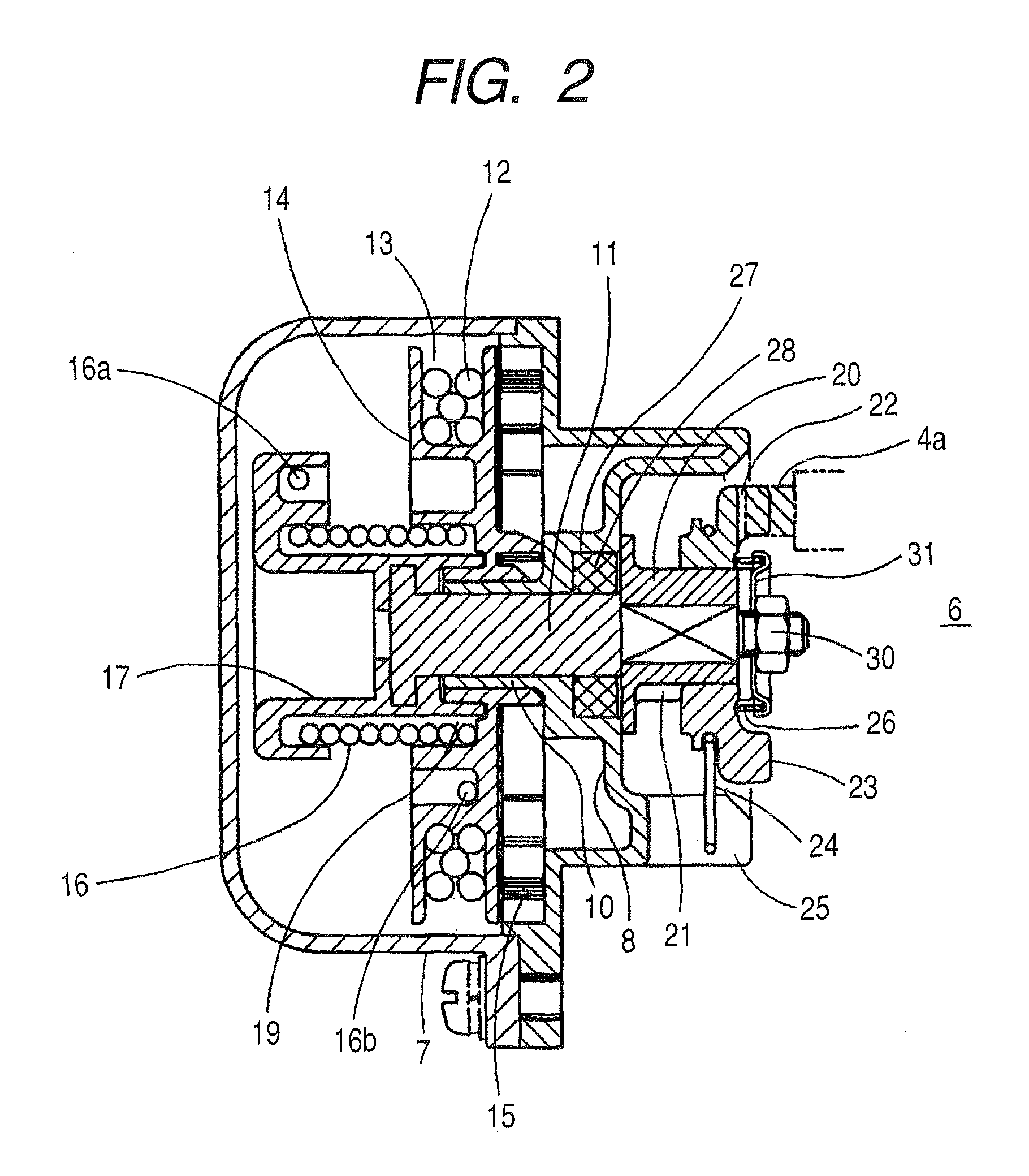
[0022]A starter case 7 that covers the recoil starter B is provided at an opening formed in the crankcase 6 of the engine A. As illustrated in detail in FIG. 2, a partition wall 8 is formed to close the opening of the crankcase 6. A cylindrical bearing 10 is formed to project from the center of the partition wall 8 toward the opposite side of th...


PUM


Abstract

A recoil starter includes a base plate that has a bearing portion formed therein and a rotary shaft that is supported by the bearing portion so as to pass through the base plate. A rope reel is rotatably supported at one side of the base plate, and a recoil rope is wound around the rope reel. A recoil spiral spring urges the rope reel to rewind the recoil rope. A damper spring has one end connected to the rotary shaft and the other end connected to the rope reel, and a clutch mechanism is disposed on an end of the rotary shaft at the other side of the base plate. The clutch mechanism transfers a rotational force to an engine.

Description

CROSS-REFERENCE TO RELATED APPLICATIONS[0001]The entire disclosure of Japanese Patent Application No. 2007-277592 filed on Oct. 25, 2007 including specification, claims, drawings and abstract is incorporated herein by reference in its entirety.BACKGROUND OF THE INVENTION[0002]1. Field of the Invention[0003]An aspect of the present invention relates to a recoil starker in which a rope reel is rotated by pulling a recoil rope wound therearound, and a rotation force of the rope reel is transferred to a clutch mechanism to start an engine via a damper spring.[0004]2. Background Art[0005]Generally, a speed adjustment unit equipped with a throttle lever is mounted on the pipe handle of a soil and vegetation management machine, such as a string trimmer, a rotary tiller, a rice transplanter or a lawn mower, and the rotation speed of an engine is controlled by adjusting the pulling amount of the throttle lever. For example, for a string trimmer, a throttle adjustment unit is mounted near a g...

Claims


Application Information

Patent Timeline
Patent Type & Authority Patents(United States)
IPC IPC(8): F02N1/00
CPCF02N3/02F02N15/022Y10T74/13
Inventor CHIGIRA, SHIGEMITSUKASAMATSU, TETSUYASHOFUDA, KENTASAITO, HIROAKIHOSHI, YUKI
Owner STARTING IND CO LTD
Why Eureka
Try Eureka