Soil remediation agent spraying device for soil remediation
A soil remediation agent, soil remediation technology
- Summary
- Abstract
- Description
- Claims
- Application Information
AI Technical Summary
Problems solved by technology
Method used
Image
Examples
Embodiment 1
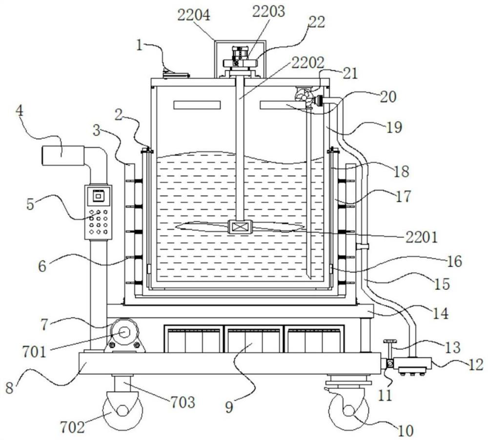
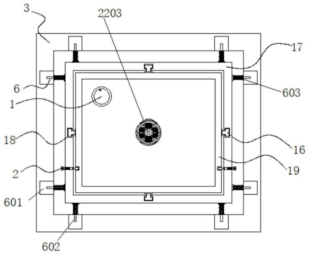
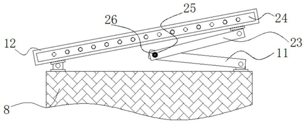
[0036] Example 1: See Figure 1-6, a soil remediation agent spraying device for soil remediation, comprising an outer frame 3 and a push handle 4, a base 8 and a support seat 14, the bottom of the base 8 is provided with a drive mechanism 7, and the other side of the base 8 bottom is fixed A universal wheel 10 is connected, a push handle 4 is welded on one side of the top of the base 8, and a controller 5 is fixedly connected to one side of the push handle 4, a battery 9 is arranged on the top of the base 8, and the top of the base 8 is fixed Connected with a support base 14, the top of the support base 14 is specified to be connected with an outer frame body 3, and the top inside the outer frame body 3 is provided with an inner frame body 17, and the top inside the inner frame body 17 is fixed with a water storage tank 19, the water storage tank 19 A stirring mechanism 22 is provided in the middle of the top of the tank, a water injection port 1 is provided on one side of the...
Embodiment 2
[0039] Embodiment 2: The fixed structure 2 is composed of a first fixed groove 201, a first movable rod 202, a first fixed spring 203, a second fixed spring 204 and a second movable rod 205, and the first movable rod 202 is arranged on the inner frame body 17 At the top of both sides, one side of the first movable rod 202 is provided with a first fixed spring 203, the top of the first movable rod 202 is provided with a second movable rod 205, and the bottom of the second movable rod 205 is provided with a second fixed spring 204, the first fixing groove 201 is arranged on both sides of the outside of the water storage tank 19, and the first fixing groove 201 and the first movable rod 202 form an engaging structure;
[0040] Specifically, such as figure 1 , figure 2 and Figure 5 As shown, since the first movable rod 202 can be pulled out after the spraying is finished, the second movable rod 205 will snap into the groove on the side of the first movable rod 202 under the ac...
Embodiment 3
[0041] Embodiment 3: The buffer structure 6 is composed of a second fixing groove 601, a third movable rod 602, a third fixing spring 603 and a limit block 604. The second fixing groove 601 is arranged on both sides and two sides of the inner frame body 17. end, the limiting block 604 is arranged on one side of the second fixing groove 601, the third fixing spring 603 is arranged on one side of the limiting block 604, and the third movable rod 602 is arranged inside the third fixing spring 603, One end of the third movable rod 602 is fixedly connected to one side of the outer frame body 3, and the third movable rods 602 are arranged at equal intervals inside the outer frame body 3;
[0042] Specifically, such as figure 1 , figure 2 and Figure 4 As shown, because there is liquid inside the device, the liquid inside the water storage tank 19 will shake and cause the device to be unstable due to inertia during the process of advancing. The fixed spring 603 buffers and weaken...
PUM
 Abstract
Description
Claims
Application Information
 - R&D
- Intellectual Property
- Life Sciences
- Materials
- Tech Scout
- Unparalleled Data Quality
- Higher Quality Content
- 60% Fewer Hallucinations
Browse by: Latest US Patents, China's latest patents, Technical Efficacy Thesaurus, Application Domain, Technology Topic, Popular Technical Reports.
© 2025 PatSnap. All rights reserved.Legal|Privacy policy|Modern Slavery Act Transparency Statement|Sitemap|About US| Contact US: help@patsnap.com


