
Apparatus and method for transmitting power headroom information in a multi-carrier system

a multi-carrier system and power headroom technology, applied in the field of wireless communication, can solve the problems of significant power consumption and the inability of bs to know the maximum transmission power value, and achieve the effect of improving uplink transmission capability and further effective transmission power control

Active Publication Date: 2012-12-13
LG ELECTRONICS INC
View PDF8 Cites 70 Cited by
  • Summary
  • Abstract
  • Description
  • Claims
  • Application Information

AI Technical Summary

Benefits of technology

[0023]According to the present invention, a base station can acquire a correct maximum transmission power value and power headroom information with respect to each component carrier allocated to a user equipment. Therefore, transmission power control can be further effectively performed with respect to each component carrier. From the perspective of the user equipment, since the maximum transmission power value and the power headroom information for each component carrier are provided to the base station, reliable carrier aggregation scheduling can be induced, thereby being able to improve uplink transmission capability.

Problems solved by technology

However, if a large bandwidth is supported even when a service request level is low, it may cause significant power consumption.
However, since the conventional PHR provides only a PH for each carrier in case of the multi-carrier system, the BS cannot exactly know a maximum transmission power value which is used as a reference for calculation of the PH.
Therefore, uplink scheduling of the BS is uncertain in some parts, and in particular, uplink transmission power scheduling depending on the PHI may cause a problem in a system (i.e., a multiple component carrier system) in which a PH for each CC needs to be individually and integrally taken into account.

Method used


Image

  • Apparatus and method for transmitting power headroom information in a multi-carrier system
  • Apparatus and method for transmitting power headroom information in a multi-carrier system
  • Apparatus and method for transmitting power headroom information in a multi-carrier system

Examples


Embodiment Construction

[0039]The technology described below can be used in various wireless communication systems such as code division multiple access (CDMA), frequency division multiple access (FDMA), time division multiple access (TDMA), orthogonal frequency division multiple access (OFDMA), single carrier frequency division multiple access (SC-FDMA), etc. The CDMA can be implemented with a radio technology such as universal terrestrial radio access (UTRA) or CDMA-2000. The TDMA can be implemented with a radio technology such as global system for mobile communications (GSM) / general packet ratio service (GPRS) / enhanced data rate for GSM evolution (EDGE). The OFDMA can be implemented with a radio technology such as institute of electrical and electronics engineers (IEEE) 802.11 (Wi-Fi), IEEE 802.16 (WiMAX), IEEE 802-20, evolved UTRA (E-UTRA), etc. IEEE 802.16m is an evolution of IEEE 802.16e, and provides backward compatibility with an IEEE 802.16-based system. The UTRA is a part of a universal mobile te...


PUM


Abstract

A method of transmitting a power headroom (PH) by a user equipment (UE) in a multi-carrier system is provided. The method includes: receiving power determination information from a base station (BS); determining a plurality of maximum transmission power values for a plurality of serving cells by using the power determination information and a UE specific parameter; determining a plurality of PHs on the basis of the plurality of maximum power transmission values; and transmitting the plurality of maximum transmission power values and the plurality of PHs to the BS. Accordingly, since the maximum transmission power value and the power headroom information are provided to the BS, reliable carrier aggregation scheduling can be induced, thereby being able to improve uplink transmission capability.

Description

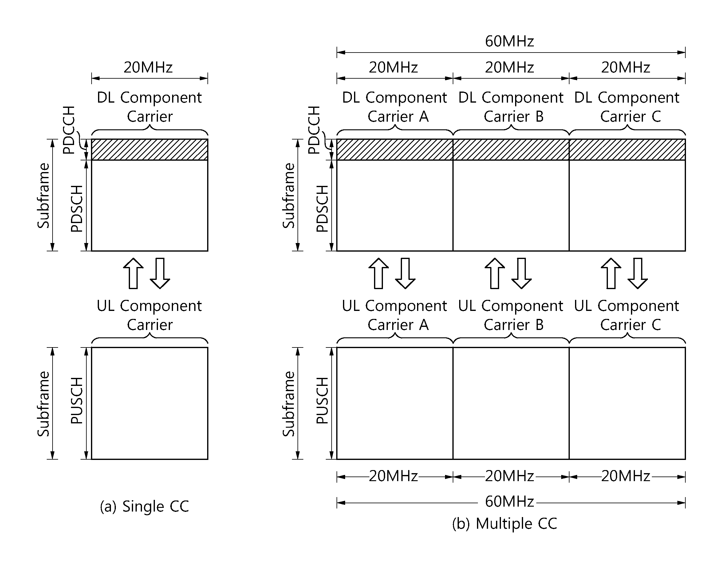
TECHNICAL FIELD[0001]The present invention relates to wireless communications, and more particularly, to an apparatus and method for transmitting power headroom information in a multi-carrier system.BACKGROUND ART[0002]In general, a wireless communication system uses one bandwidth for data transmission. For example, a 2nd generation wireless communication system uses a bandwidth of 200 KHz˜1.25 MHz, and a 3rd generation wireless communication system uses a bandwidth of 5 MHz˜10 MHz. To support growing transmission capacity, the 3rd generation partnership project (3GPP) long term evolution (LTE) or the institute of electrical and electronics engineers (IEEE) 802.16m has recently expanded its bandwidth to 20 MHz or higher. It may be necessary to increase the bandwidth to obtain high transmission capacity. However, if a large bandwidth is supported even when a service request level is low, it may cause significant power consumption.[0003]Therefore, a carrier having one bandwidth and a ...

Claims


Application Information

Patent Timeline
IPC IPC(8): H04W52/02
CPCH04L5/001H04W52/365H04L5/0053H04W52/16H04W52/325H04W52/34H04W52/367H04W24/10H04W52/30H04W72/23
Inventor KIM, MIN GYUYANG, SUCK CHELAHN, JOON KUISEO, DONG YOUN
Owner LG ELECTRONICS INC
Learn More