
Circuit breaker with high speed mechanically-interlocked grounding switch

A circuit breaker and electrical connection technology, applied in the field of vacuum circuit breakers, can solve problems such as overvoltage, and achieve the effect of small energy loss and low cost

Active Publication Date: 2013-06-05
EMA ELECTROMECANICA
View PDF4 Cites 0 Cited by
  • Summary
  • Abstract
  • Description
  • Claims
  • Application Information

AI Technical Summary

Problems solved by technology

An overvoltage condition occurs if the switch does not toggle within a maximum of three cycles

Method used


Image

  • Circuit breaker with high speed mechanically-interlocked grounding switch
  • Circuit breaker with high speed mechanically-interlocked grounding switch
  • Circuit breaker with high speed mechanically-interlocked grounding switch

Examples


Embodiment Construction

[0092] The present invention will be described in further detail below in combination with specific embodiments and with reference to the accompanying drawings.

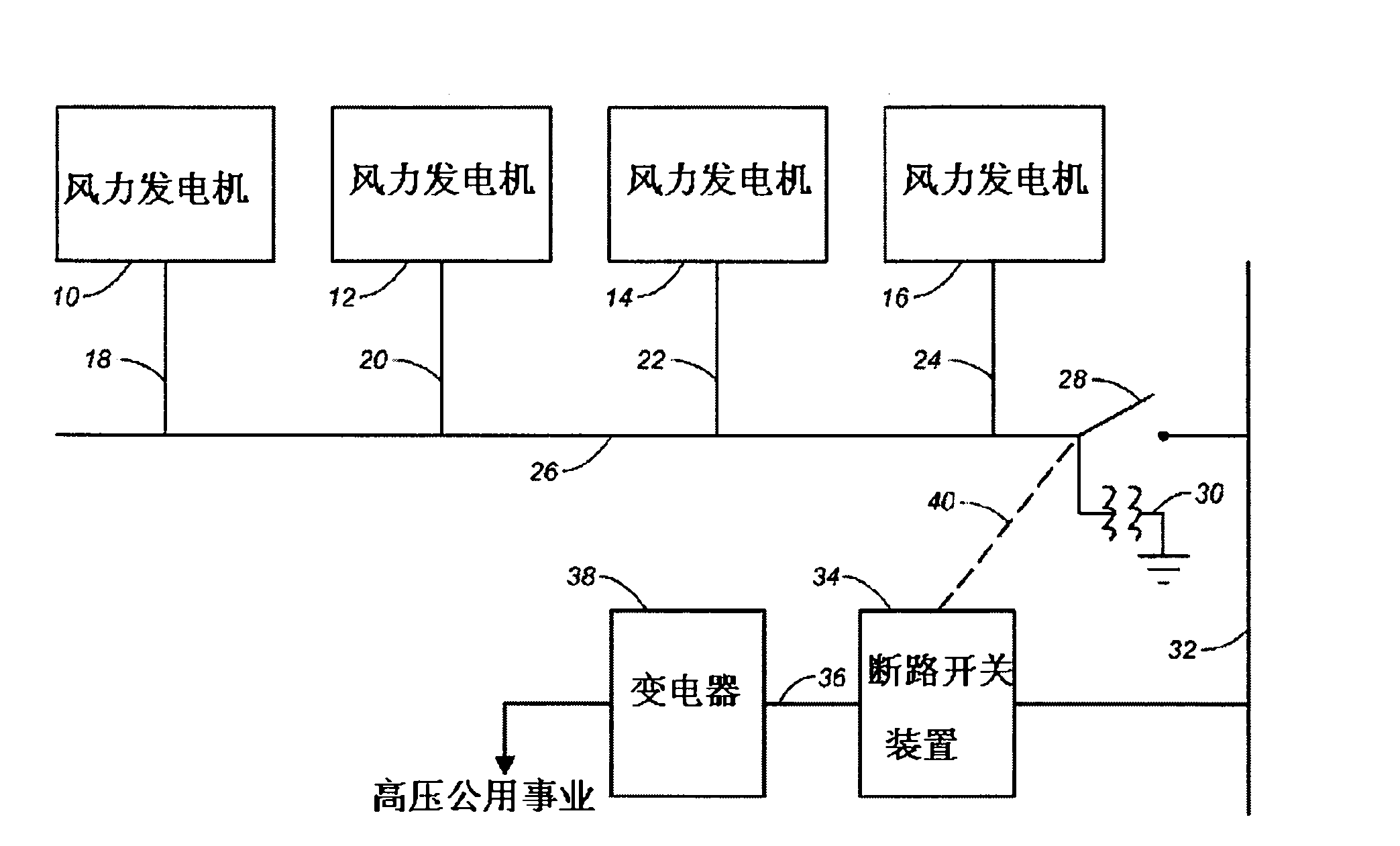
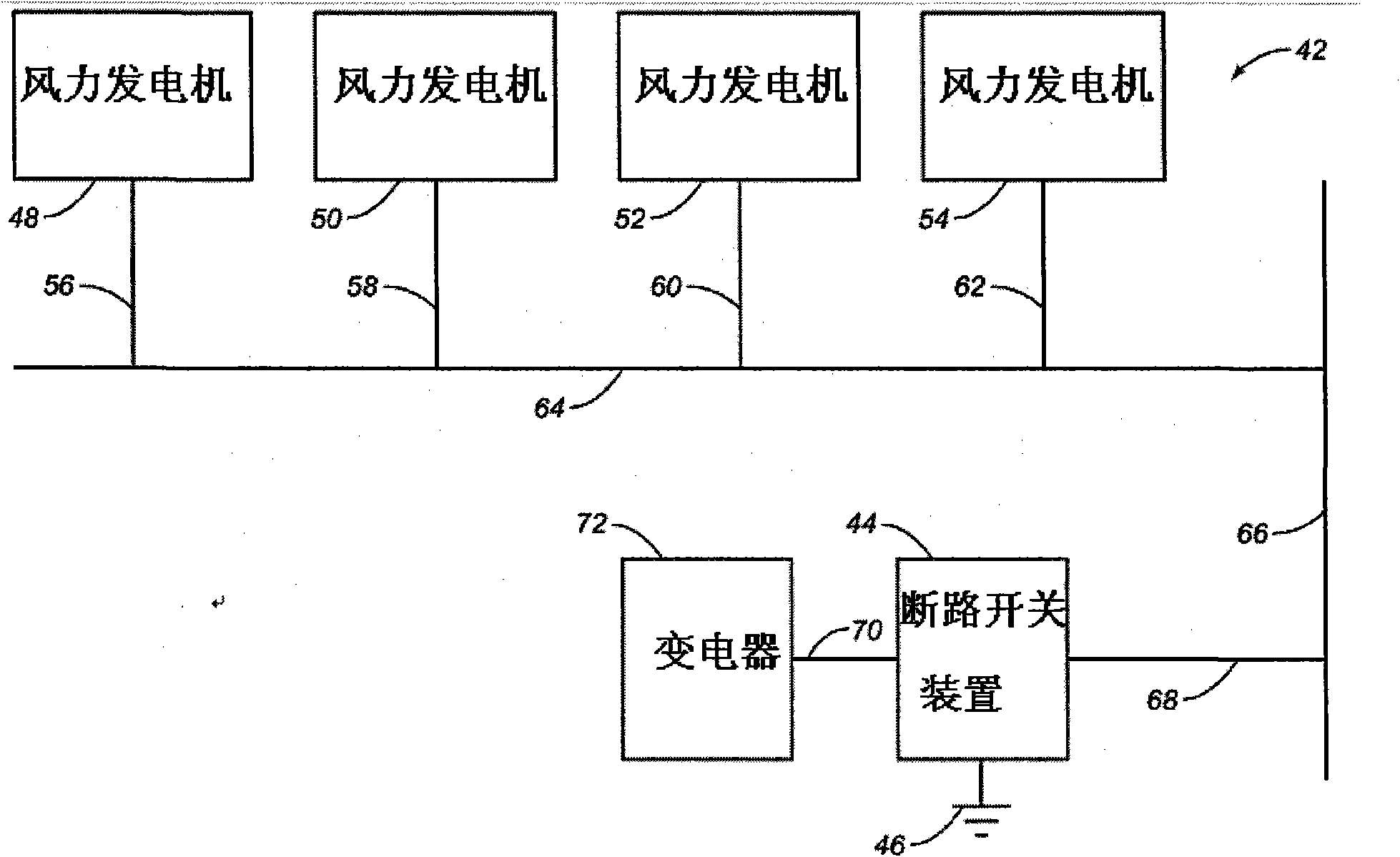
[0093] Such as figure 2 Shown is the system 42 of the present embodiment, the disconnect switch system 42 of the present embodiment includes a disconnect switch device 44 for transferring energy to ground through an open circuit. A plurality of wind turbines 48 , 50 , 52 , 54 are respectively connected to corresponding conductors 56 , 58 , 60 , 62 to the busway 64 . The wind generators 48, 50, 52, 54 may be part of a windmill farm. The different manifolds 64 can also be reconnected to one main energy transfer manifold 66 . Ultimately, energy is transferred along the wire 68 to the disconnect switch device 44 . When the disconnect switch device 44 is properly closed, energy will be transferred along the conductor 70 to the transformer 72 . Such as figure 2 As shown, the busway 64 does not include the ground trans...


PUM


Abstract

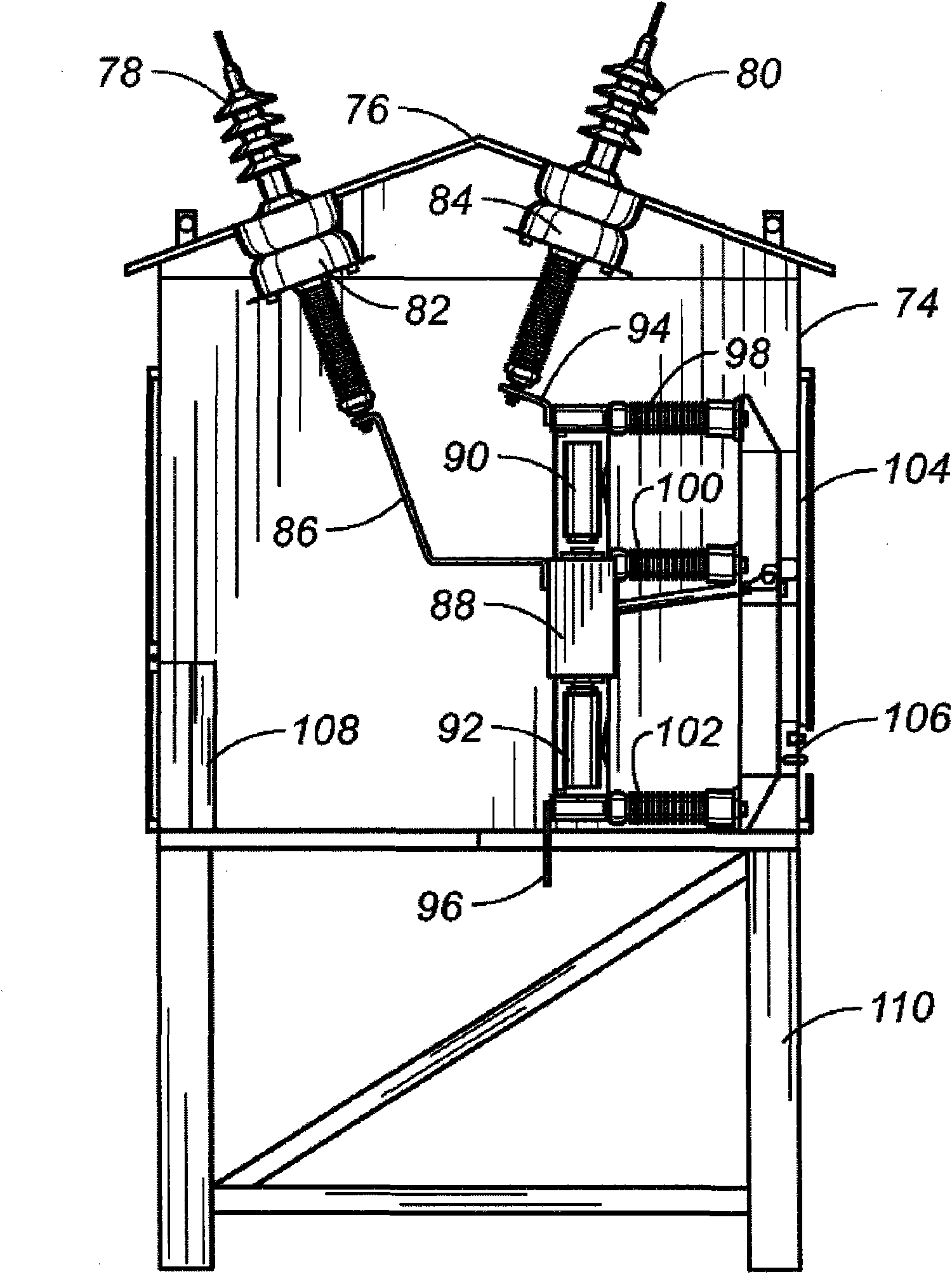
A circuit breaker apparatus with an integrated grounding switch has a housing with first and second bushings extending outwardly of the housing. A first vacuum bottle is positioned in the housing and has a pair of contactors therein. A second vacuum bottle is positioned in the housing and has a pair of contactors therein. A mechanical linkage is movable between a first position and a second position. The first position electrically connects the first bushing to the second bushing. The second position electrically connects the first bushing to ground. The first vacuum bottle and the second vacuum bottle are longitudinally aligned. The mechanical linkage is interposed between the first and second vacuum bottles.

Description

technical field [0001] The invention relates to a vacuum circuit breaker switch device, in particular to a circuit breaker switch device with a mechanical interlocking grounding switch which is matched with a power collection circuit of a windmill farm. Background technique [0002] Windmill farms are becoming more and more common because they generate electricity. In windmill farms, a large number of wind turbines are installed in rural areas where the wind is continuous and strong. Generally speaking, a wind generator includes a plurality of sets of blades connected to a rotating shaft, and the rotating shaft is driven by the rotation of the blades to generate electricity. Wires connect the generators to transfer energy from specific wind turbines to the collection manifold. The electricity generated by the different wind turbines in the windmill farm can be sent to the transformer. [0003] Generally, each wind turbine can have an output power of 500 kilowatts to 3500 ...

Claims


Application Information

Patent Timeline
Patent Type & Authority Patents(China)
IPC IPC(8): H01H33/66H01H33/28
CPCH01H33/666H01H31/003H01H2033/6667
Inventor 洛根·纳普
Owner EMA ELECTROMECANICA
Learn More