Hoisting system of large-sized extensible antenna

An antenna and large-scale technology, applied in the field of hoisting systems and temporary awnings, can solve the problems of high manufacturing cost of frictionless cylinders, rare large-scale deployable devices, and inability to meet the requirements of complex motion trajectories of deployed antennas, and reduce the number of tests. cost effect

Inactive Publication Date: 2011-05-11
XIDIAN UNIV
View PDF5 Cites 10 Cited by
  • Summary
  • Abstract
  • Description
  • Claims
  • Application Information

AI Technical Summary

Problems solved by technology

This method has two obvious defects: it must be hung indoors, and the application height and span are limited; due to the use of complex devices such as motors, force sensors, and displacement sensors, it is inconvenient to install, debug, and withdraw
This method also has three major defects: this method can only realize the movement in the vertical direction, and cannot meet the requirements of the complex motion trajectory of the unfolded antenna; this method cannot meet the test requirements of the large flexibility of the test object that requires multi-point unloading; manufacturing cost is too high
[0006] Although there are a variety of ground test deployment devices based on spaceborne deployable antennas, large-scale deployable devices with excellent comprehensive characteristics are rare

Method used


Image

  • Hoisting system of large-sized extensible antenna
  • Hoisting system of large-sized extensible antenna
  • Hoisting system of large-sized extensible antenna

Examples


example 1

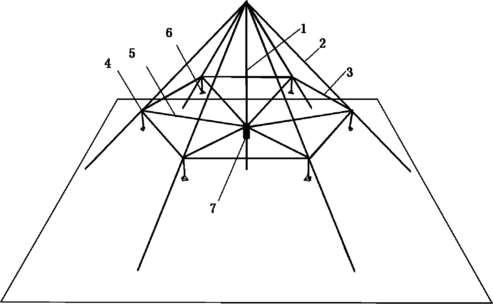
[0032] Example 1, the deployment of a deployable antenna with a diameter of 10 m under the device of the present invention.

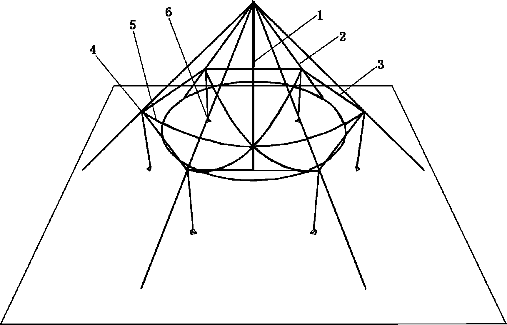
[0033] The collapsed state of the device is as figure 1 As shown, the expanded state is as figure 2 shown.

[0034] The central column adopts a movable lifting rod, and the height after stretching is 12 meters; the test uses 6 positioning cables, each of which is 17 meters long, and is 45 degrees away from the lifting rod; a Kevlar support cable with a length of 42.43m; 6 6 suspension rings; 6 Kevlar traction cables; after deployment, the apex of the antenna is 1 meter from the bottom of the lifting rod; the weight of the antenna is 24 kg, and each counterweight is 4.5 kg; 0.5.

[0035] The simulation analysis of the reflective surface under the device shows that the maximum deformation occurs on the ring, the maximum deformation is 15mm, and the surface root mean square error RMS is 6mm. It can be seen that the unloading effect is still very ideal. ...

example 2

[0036] Example 2, the deployment of a deployable antenna with a diameter of 20m under the device of the present invention.

[0037] The folded state of the device is as Figure 4 As shown, the expanded state with cablenet installed is as follows Figure 5 shown.

[0038] The central column adopts a fixed lifting rod, and the height after stretching is 20m; due to the large diameter of the antenna, in order to ensure the accuracy of the unfolded antenna profile, more unloading points are used here. A total of 12 positioning cables are used for unloading, and steel strands are also used. After being unfolded, they are tightened with a winch. A traction cable, also made of Kevlar fiber material; 12 suspension rings; 12 counterweights; the antenna diameter is 20m, the focal diameter ratio is 0.5, the top base of the apex is 3m, the total weight is 84kg, and each counterweight is 9kg.

[0039] The simulation analysis of the reflective surface under the device shows that the maxi...

example 3

[0040] Example 3, an expandable flexible awning with a diameter of 30m.

[0041] The folded state of the device is as Figure 6 As shown, the expanded state is as Figure 7 shown.

[0042] The central column 201 adopts a fixed pillar and is 20 meters high; the positioning cable 202 has 6 sections in total, using steel strands, and the winch is tightened after pulling, and each section is 40 meters long; correspondingly, 6 lifting rings 203 are used; 6 counterweights 205 , each counterweight is 10 kg; the total weight of the awning is 102 kg, and the hoisting height is 18 meters. Due to the limit of the boundary size of the awning itself, the counterweight will stop sliding when it is pulled to a certain position. This device can provide an idea for quickly building a temporary sunshade.


PUM


Abstract

The invention discloses a hoisting system for a large-sized extensible antenna, and in particular relates to a ground testing system for the extensible antenna. The hoisting system provided by the invention mainly solves the problem that the existing testing system can not simulate the space zero gravity extension for the extensible antenna in the ground stimulation. The system provided by the invention comprises a lifting rod (1), a positioning cable (2), a supporting cable (3), a hoisting ring (4), a pulling cable (5) and a counter weight (6), wherein the supporting cable (3) is an equilateral polygon parallel to the opening surface of the extensible antenna (7); the hoisting ring (4) is arranged in each cross position of the radially arranged positioning cable (2) and supporting cable (3); the pulling cable (5) passes through the hoisting ring (4) and is respectively connected with the counter weight (6) and the extensible antenna (7); and one end of the positioning cable (2) is connected with the upper end of the lifting rod (1), and the other end of the positioning cable and the other end of the lifting rod are fixed with the ground so as to form a circular conical surface extensible supporting structure with the lifting rod (1) as the center. The hoisting system provided by the invention is convenient in gravity unloading, is not limited by the testing space and can be used for the ground extension test of the extensible antenna.

Description

technical field [0001] The invention belongs to the field of mechanical technology, specifically a hoisting system, which is mainly applied to the ground deployment test of space-borne ring-rib deployable antennas, and can also be applied to the ground deployment tests of other types of deployable antennas and temporary awnings on the ground . Background technique [0002] With the development of space communication technology and the demand for deep space exploration, the aperture of the antenna is getting larger and larger. Due to the limitation of the carrying capacity and carrying space of the satellite, the space-borne deployable antenna has emerged as the times require. Generally, space-borne deployable antennas have three states: the folded state, the intermediate transition state from the folded state to the unfolded state, and the unfolded state that remains locked to the working state. However, due to the complex space environment, it is difficult to achieve impres...

Claims


Application Information

Patent Timeline
Patent Type & Authority Applications(China)
IPC IPC(8): B66F11/00
Inventor 郑飞陈梅刘代明梁志刚张久利项斌斌林上民
Owner XIDIAN UNIV
Why Eureka
Try Eureka