Fuel supply device

A fuel supply device and fuel technology, which are applied to liquid fuel feeders, charging systems, combustion engines, etc., can solve the problems of fuel supply failure and engine restart, and achieve the effect of reducing fuel supply failure

Inactive Publication Date: 2011-05-11
MITSUBISHI ELECTRIC CORP
View PDF5 Cites 0 Cited by
  • Summary
  • Abstract
  • Description
  • Claims
  • Application Information

AI Technical Summary

Problems solved by technology

[0005] However, this kind of fuel supply device has the following problem: when the amount of fuel in the fuel tank is relatively small, when trying to restart the vehicle body stopped in an inclined posture, if the suction port of the suction passage communicating with the fuel pump is located at a lower position than the If the surface of the fuel is still close to the upper position, it is possible that the engine cannot be started due to the lack of fuel supply

Method used


Image

  • Fuel supply device
  • Fuel supply device
  • Fuel supply device

Examples


Embodiment approach 1

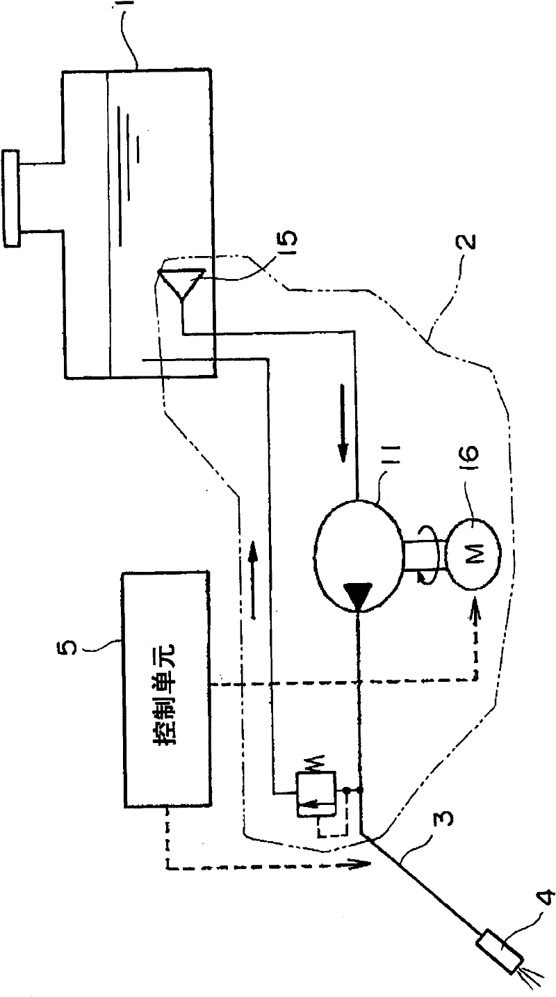
[0019] figure 1 It is a configuration diagram showing a fuel supply system incorporating the fuel supply device according to Embodiment 1 of the present invention.

[0020] The fuel supply system includes: a fuel tank 1; a fuel supply device 2 according to Embodiment 1 of the present invention, which is directly installed on the bottom surface of the above-mentioned fuel tank 1; A fuel supply device 2 is connected to inject fuel supplied from the fuel supply device 2 into a fuel chamber (not shown); and a control unit 5 that controls the fuel supply from the fuel supply device 2 to the fuel injection valve 4 and the fuel Injection time of injection valve 4.

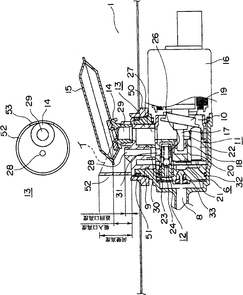
[0021] figure 2 It is a partially cutaway sectional view of the fuel supply device 2 . In addition, a plan view of the adapter 13 is also shown in the figure.

[0022] The fuel supply device 2 includes: a casing 6 having a high-pressure fuel passage 8 and an opening 9 on the side of the fuel tank 1; The fuel is pres...

Embodiment approach 2

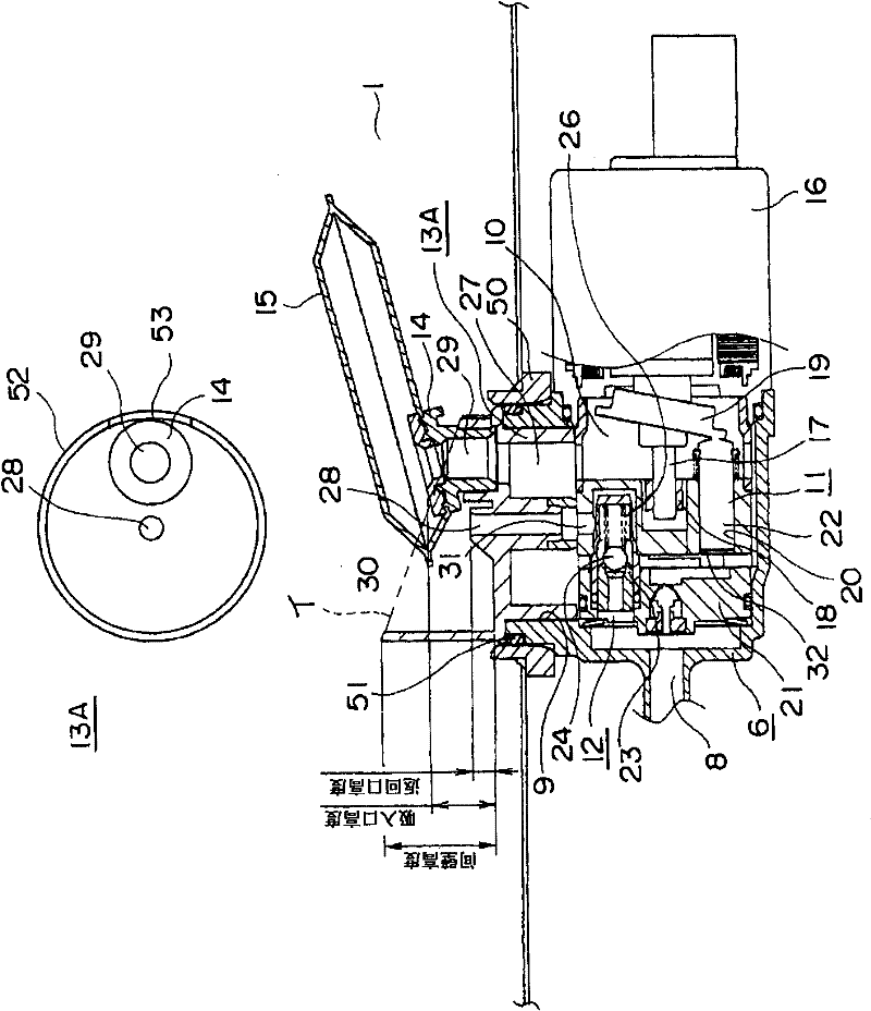
[0053] image 3 is a partial sectional view of the fuel supply device 2 . In addition, a plan view of the adapter 13A is also shown in the figure.

[0054] In the adapter 13A of the present embodiment, the return port of the return passage 28 is formed at the center of the circular partition wall 52 as viewed in the axial direction.

[0055] Other configurations are the same as those of the fuel supply device in Embodiment 1.

[0056] In this fuel supply device 2, since the return port of the return passage 28 is formed at the center of the adapter 13A, the circumferential direction of the adapter 13A can be changed around the return port without changing the installation position of the fuel supply device 2 on the fuel tank 1 . The position, that is, the position of the filter 15 connected to the suction passage 27 through the mounting member 14 can be changed.

[0057] Furthermore, since the filter 15 can be arranged arbitrarily in the circumferential direction with respe...

Embodiment approach 3

[0060] Figure 4 is a partial sectional view of the fuel supply device 2 . In addition, a plan view of the adapter 13B is also shown in the figure.

[0061] In this embodiment, the main body of the adapter 13B fitted into the opening 9 of the housing 6 is made of hard resin, and only the partition wall 52A is made of an elastic member such as rubber.

[0062] Other configurations are the same as those of the fuel supply device in Embodiment 1.

[0063] When the fuel supply device 2 is attached to the device attachment hole of the fuel tank 1, the filter 15 is attached to the adapter 13B via the attachment member 14 before attachment.

[0064] At this time, when the filter 15 faces upward, the partition wall of the adapter will not become an obstacle to installation, but if the filter 15 is substantially parallel to the bottom surface of the fuel tank 1, the partition wall will become an obstacle to installation.

[0065] In contrast, in this embodiment, since the partition ...


PUM


Abstract

The invention provides a fuel supply device, wherein the short supply of fuel due to the inclination of the fuel in a fuel tank is avoided without changing the appearance of the fuel tank.The fuel supply device comprises an inhalation path (27) for inhaling fuel into the fuel tank (1), a return path (38) for the return of fuel flowing out of a pressure adjustment body (12) to the fuel tank (1) and an adapter (13). The partition of the adapter (13) surrounds the suction inlet of the inhalation path (27) and the return port of the return path (38).The fuel supply device also comprises an incision (53) communicating with the interior of the fuel tank (1).

Description

technical field [0001] The present invention relates to a fuel supply device incorporating a pressure regulating body for regulating the pressure of fuel supplied to an engine of a small motorcycle or the like. Background technique [0002] The applicant of this application previously applied for a fuel supply device, which is installed on the bottom surface of the fuel tank of the vehicle body, and supplies the fuel in the fuel tank to the fuel injection valve through a high-pressure pipe, including: a housing, the housing is installed The above-mentioned fuel tank has an opening and a high-pressure fuel passage communicating with the above-mentioned high-pressure pipe; a fuel pump, which is installed in the above-mentioned casing, and pressurizes the above-mentioned fuel; a pressure regulator, which is installed on the above-mentioned inside the casing, the fuel delivered from the fuel pump to the high-pressure fuel passage is adjusted to a predetermined pressure; and an a...

Claims


Application Information

Patent Timeline
Patent Type & Authority Applications(China)
IPC IPC(8): F02M37/00F02M37/08
CPCY02T10/12
Inventor 尾岛宏一津上弘道大西善彦
Owner MITSUBISHI ELECTRIC CORP
Why Eureka
Try Eureka