Disk hot standby method and device as well as storage system

A storage system and disk technology, applied in the direction of input/output to record carrier, etc., can solve the problems of low hot backup efficiency, unusable space for data storage, waste of hot backup disk storage space, etc.

Inactive Publication Date: 2011-05-11
HUAWEI DIGITAL TECH (CHENGDU) CO LTD
View PDF3 Cites 7 Cited by
  • Summary
  • Abstract
  • Description
  • Claims
  • Application Information

AI Technical Summary

Problems solved by technology

[0003] The inventor has found in practice that the above-mentioned hot spare disk only plays a role when the disk fails, and under normal circumstances, the space on the hot spare disk cannot be used for data storage, which greatly wastes the storage space of the hot spare disk. Moreover, since only one disk can be reconstructed or copied back in RAID at a time, only one disk can be hot-backed up in RAID at a time, and the hot-backup efficiency of RAID is low.

Method used


Image

  • Disk hot standby method and device as well as storage system
  • Disk hot standby method and device as well as storage system
  • Disk hot standby method and device as well as storage system

Examples


Embodiment 1

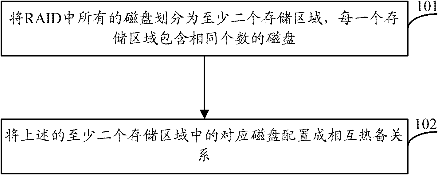
[0025] see figure 1 , figure 1 It is a schematic flowchart of a disk hot backup method provided by an embodiment of the present invention. Such as figure 1 As shown, the disk hot backup method may include the following steps:

[0026] 101. Divide all the disks in the RAID into at least two storage areas, and each storage area contains the same number of disks;

[0027] In this embodiment of the present invention, the type of RAID may be RAID5, RAID6, RAID50, etc. of distributed parity, which is not limited in this embodiment of the present invention.

[0028] 102. Configure the corresponding disks in the above at least two storage areas to be in a mutual hot standby relationship.

[0029] In the embodiment of the present invention, the corresponding disks in the above at least two storage areas may specifically be the same disks in each storage area; wherein, the disks in each storage area are sorted according to the disk serial number from small to large.

[0030] In Emb...

Embodiment 2

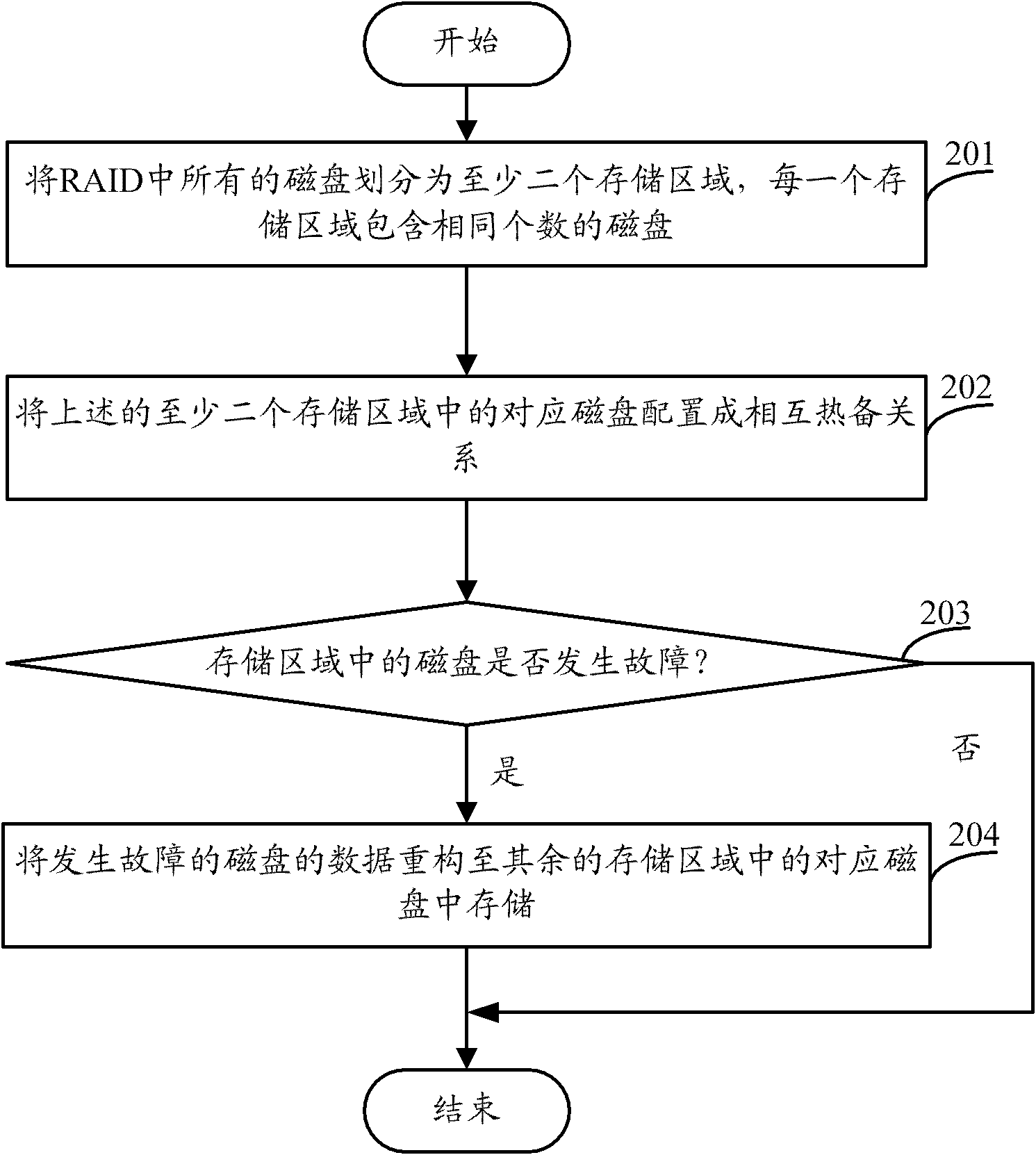
[0032] see figure 2 , figure 2 It is a schematic flowchart of another disk hot backup method mentioned in the embodiment of the present invention. Such as figure 2 As shown, the disk hot backup method may include the following steps:

[0033] 201. Divide all the disks in the RAID into at least two storage areas, and each storage area contains the same number of disks;

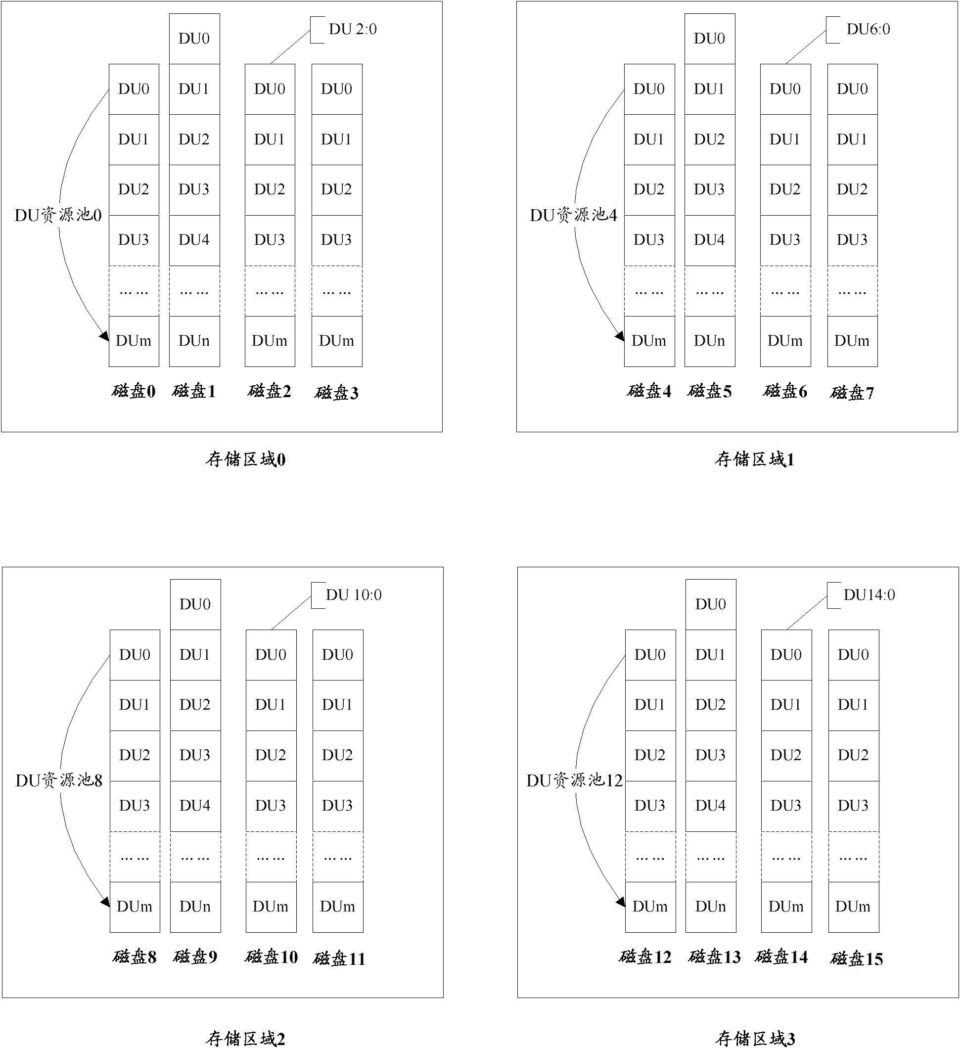
[0034] For example, assuming that the RAID includes 16 disks, namely disk 0 to disk 15, all the disks in the RAID can be divided into 4 storage areas, namely storage area 0, storage area 1, storage area 2, and storage area Area 3, wherein each storage area includes 4 disks. Such as image 3 As shown, after all disks in the RAID are divided into storage area 0 to storage area 3, storage area 0 includes 4 disks, namely disk 0, disk 1, disk 2, and disk 3; storage area 1 also includes 4 disks. Disk 4, Disk 5, Disk 6, and Disk 7; storage area 2 also includes 4 disks, namely Disk 8, Disk 9, Disk 10, and Disk...

Embodiment 3

[0054] see Figure 5 , Figure 5 It is a schematic structural diagram of a disk hot backup device mentioned in the embodiment of the present invention. Wherein, the hot disk backup device 500 may include:

[0055] A division unit 501, configured to divide all the disks in the inexpensive redundant disk array into at least two storage areas, each of which contains the same number of disks;

[0056] The configuring unit 502 is configured to configure the corresponding disks in the at least two storage areas divided by the dividing unit 501 into a mutual hot standby relationship.

[0057] In the embodiment of the present invention, the above-mentioned corresponding disks may specifically be the same disks in each storage area; wherein, the disks in each storage area are sorted from small to large disk serial numbers.

[0058] As an optional implementation manner, the configuration unit 502 may be specifically configured to configure the corresponding disks in the at least two ...


PUM


Abstract

The embodiment of the invention relates to the technical field of hot standby and discloses a disk hot standby method and device as well as a storage system. The disk hot standby method comprises the following steps: dividing all disks in a cheap redundancy disk array into at least two storage areas, wherein each storage area contains same number of disks; and configuring the corresponding disks in the at least two storage areas into hot standby relation. According to embodiment of the invention, no reserved extra hot standby storage space is required, and the hot standby efficiency of the cheap redundancy disk array can be increased.

Description

technical field [0001] The invention relates to the technical field of hot backup, in particular to a disk hot backup method and device, and a storage system. Background technique [0002] Currently, a traditional storage system usually utilizes an inexpensive redundant disk array (Redundant Arrays of Inexpensive Disks, RAID) technology to achieve data reliability and concurrency. In order to achieve data security redundancy in the RAID, one or more hot spare disks are usually specially arranged in the RAID. Once a certain disk in the RAID fails, the data on the faulty disk will be reconstructed to the hot spare disk to realize the hot backup of the faulty disk; after the faulty disk is replaced with a new disk, the data on the hot spare disk will be Data is copied back to the new disk. In this way, when a disk in the RAID fails, it will not affect the use of the entire disk array. [0003] The inventor has found in practice that the above-mentioned hot spare disk only pl...

Claims


Application Information

Patent Timeline
Patent Type & Authority Applications(China)
IPC IPC(8): G06F3/06
Inventor 林宇方敏
Owner HUAWEI DIGITAL TECH (CHENGDU) CO LTD
Why Eureka
Try Eureka