Device for sealing steel balls in battery shells

A battery shell and steel ball technology, which is applied in secondary battery manufacturing, battery pack components, circuits, etc., can solve problems such as high labor intensity, battery scrapping, and quality assurance, and achieve the effect of reducing labor intensity

Inactive Publication Date: 2011-05-18
CHERY AUTOMOBILE CO LTD
View PDF4 Cites 10 Cited by
  • Summary
  • Abstract
  • Description
  • Claims
  • Application Information

AI Technical Summary

Problems solved by technology

[0003] At present, many battery manufacturers basically use a hammer to seal the steel ball after battery injection and primary formation, but there are many disadvantages in this way. Strength, the depth of the steel balls knocked on each battery is not consistent, and it is easy to knock the steel balls into the battery and cause the battery to be scrapped
Second: Because the steel ball holes are covered with adhesive tape after one-time formation, the adhesive tape is usually torn off in the drying room and then knocked on the steel ball. Generally, the dew point of the drying room is not very low, and employees need to enter the drying room to operate, which increases the The humidity in the drying room is reduced, which will easily cause the humidity to invade the inside of the battery and affect the quality of the battery.
There are also many manufacturers who adopt the method of sealing steel balls after vacuuming, which requires a complete set of relatively large and precise working system. Although the quality of sealing steel balls is guaranteed, the production cost is relatively high.
[0004] In the process of realizing the present invention, the inventor found that the prior art has at least the following problems: the existing steel ball sealing method for the lithium battery case, or the sealing depth cannot be kept consistent, the labor intensity is high, the quality cannot be guaranteed, or the production cost is high

Method used


Image

  • Device for sealing steel balls in battery shells
  • Device for sealing steel balls in battery shells
  • Device for sealing steel balls in battery shells

Examples


Embodiment Construction

[0021] In order to make the object, technical solution and advantages of the present invention clearer, the implementation manner of the present invention will be further described in detail below in conjunction with the accompanying drawings.

[0022] As shown in the figure, the technical solution of the embodiment of the present invention is:

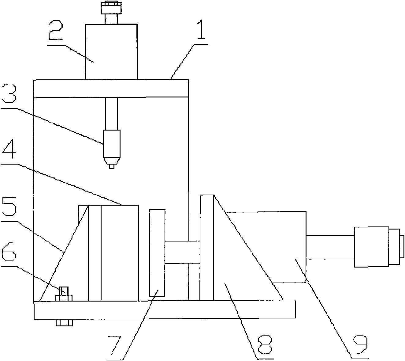
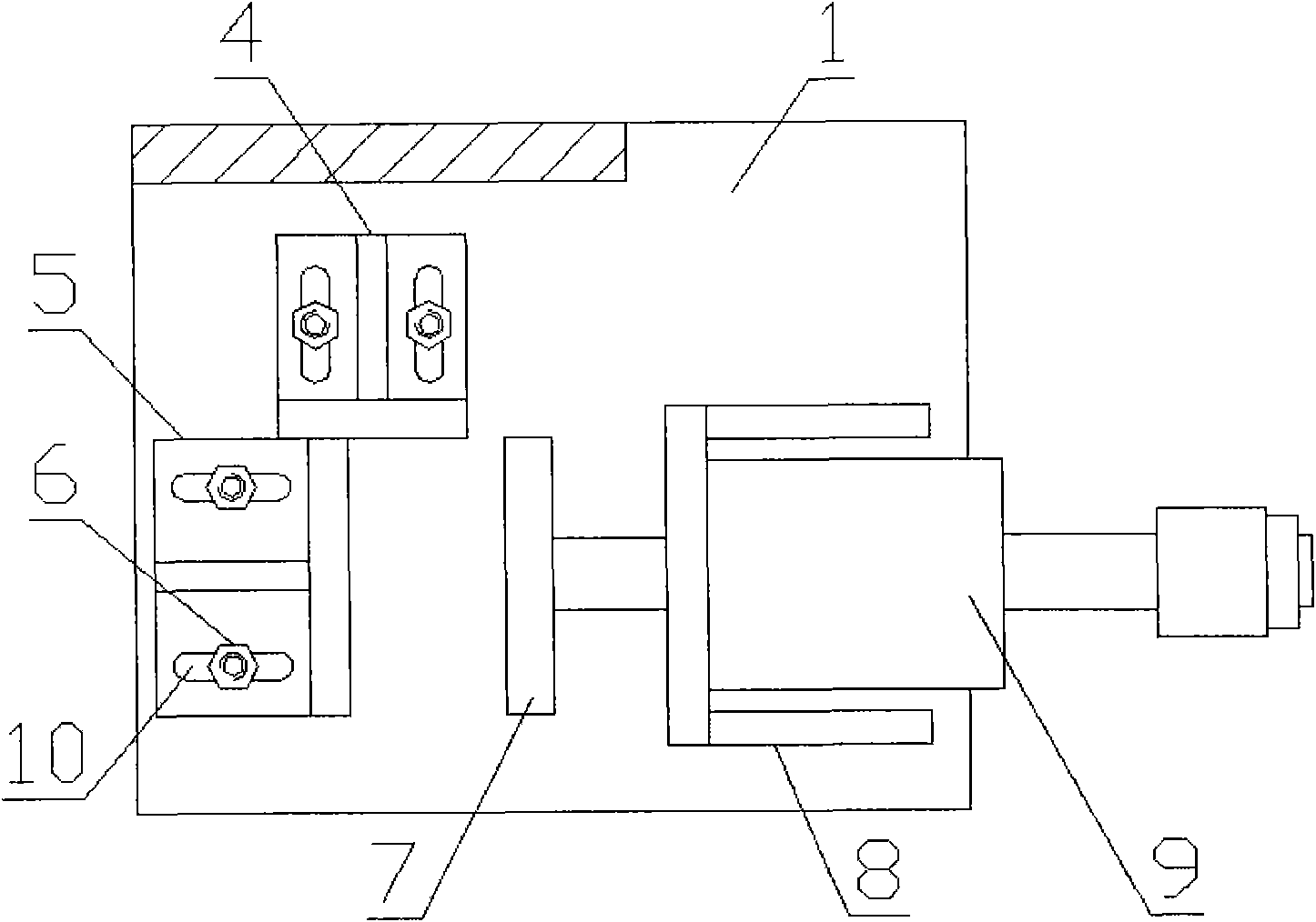
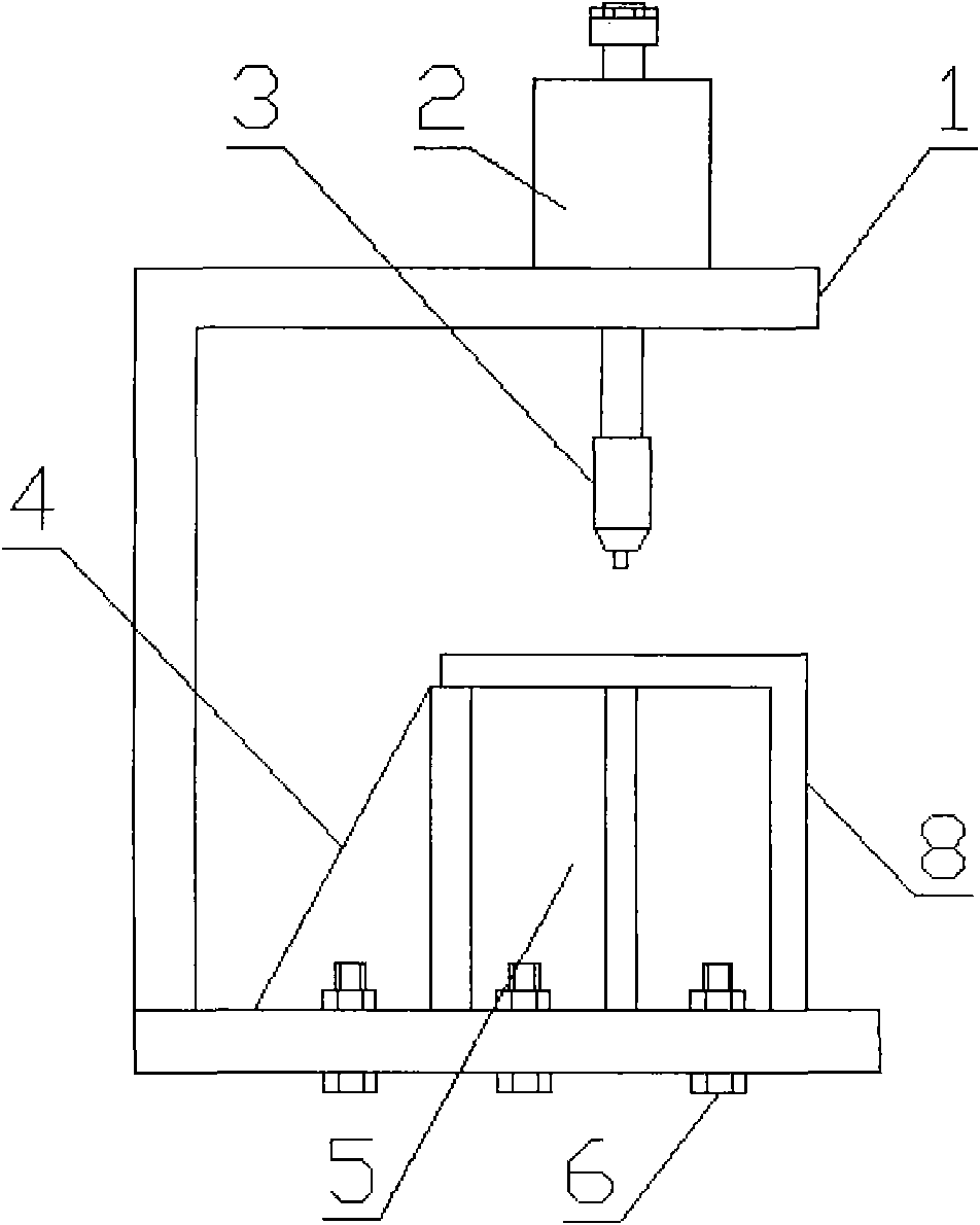
[0023] A battery case sealing steel ball device, comprising a device body 1, a battery case positioning mechanism is arranged on the device body 1, a steel ball punching mechanism is arranged above the battery case positioning mechanism, and the battery case positioning mechanism includes a vertically arranged X-axis Positioning seat 4 and Y-axis positioning seat 5.

[0024] The steel ball stamping mechanism is arranged on the device body 1 , and includes a steel ball stamping cylinder 2 located above and a stamping head 3 located below, and the steel ball stamping cylinder 2 is fixedly arranged on the device body 1 .

[0025] The op...


PUM


Abstract

The invention discloses a device for sealing steel balls in battery shells, which comprises a device body, wherein the device body is provided with a battery shell positioning mechanism; a steel ball stamping mechanism is arranged above the battery shell positioning mechanism; the battery shell positioning mechanism comprises an X-axis positioning seat and a Y-axis positioning seat which are vertical to each other; a shaping movable plate is arranged opposite to the X-axis positioning seat or a Y-axis positioning seat; and the rear end of the shaping movable plate is provided with a shaping cylinder. The device has the advantages that: the positions of the battery shells are limited or fixed through the battery shell positioning mechanism, the steel balls are arranged at steel ball holes and are stamped by the steel ball stamping mechanism so as to seal the steel balls in the shells, the steel ball stamping force and depth are consistent, and the labor intensity is reduced; meanwhile, a shaping mechanism consisting of the shaping cylinder and the shaping movable plate is arranged, surplus gas in the shells is eliminated before the steel balls are sealed, and the deformation of the shells is strictly controlled.

Description

technical field [0001] The invention relates to the technical field of battery processing, in particular to a steel ball sealing device for a battery case. Background technique [0002] Lithium-ion batteries are widely used in products such as notebook computers, video cameras, digital cameras, mobile phones, and power tools. Especially in today's rapidly developing society, traditional energy sources such as oil, coal, and natural gas are decreasing as people increasingly exploit them. A new generation of batteries --- lithium-ion batteries, fuel cells, and other clean, environmentally friendly, and efficient energy conversions Energy storage system has become an effective method to solve the environmental and energy problems faced by modern civilization, and is favored by people. [0003] At present, many battery manufacturers basically use a hammer to seal the steel ball after battery injection and primary formation, but there are many disadvantages in this way. The dep...

Claims


Application Information

Patent Timeline
Patent Type & Authority Applications(China)
IPC IPC(8): H01M2/02H01M10/04
CPCY02E60/12Y02E60/10Y02P70/50
Inventor 张海军
Owner CHERY AUTOMOBILE CO LTD
Why Eureka
Try Eureka