Waveguide flat array antenna

An array antenna and waveguide technology, applied in antennas, antenna coupling, antenna arrays, etc., can solve the problems that flat-panel antennas cannot meet the system requirements at the same time, cannot meet the system use requirements, and are not easy to mass-produce, so as to reduce the feeding network layer Number, efficiency improvement, avoiding the effect of welding process

Inactive Publication Date: 2011-05-18
李峰
View PDF3 Cites 36 Cited by
  • Summary
  • Abstract
  • Description
  • Claims
  • Application Information

AI Technical Summary

Problems solved by technology

The microstrip panel antenna generally forms a feeding network by microstrip, stripline, etc., and the radiation unit usually chooses a microstrip patch, a slot, etc., and the panel antenna composed of a dielectric material, when the frequency increases (especially X~Ka band), the feed loss increases rapidly, seriously affecting the gain
There are two main types of waveguide slot arrays: standing wave array and traveling wave array. Compared with microstrip and other antennas using printing technology, their manufacturing costs are high.
Usually requires a welding process and is not easy to mass produce
At the same time, the bandwidth of the standing wave array is limited by the size of the sub-array, which generally does not exceed 10%. Although the bandwidth of the traveling wave array can be greater than 10%, the beam pointing changes with the frequency, and the beam width increases accordingly, and the gain decreases.
It cannot meet the system requirements under fixed installation conditions such as point-to-point communication
At the same time, the presence of absorbing loads at the end of the array further reduces the antenna efficiency
Therefore, in systems requiring broadband and high efficiency, neither of these two types of panel antennas can meet the system requirements at the same time.

Method used


Image

  • Waveguide flat array antenna
  • Waveguide flat array antenna
  • Waveguide flat array antenna

Examples


Embodiment Construction

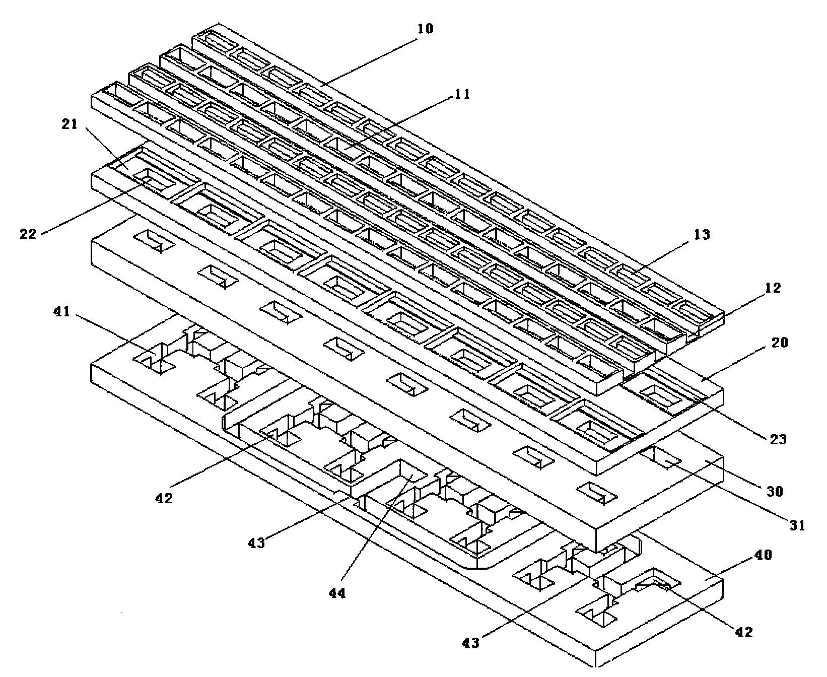
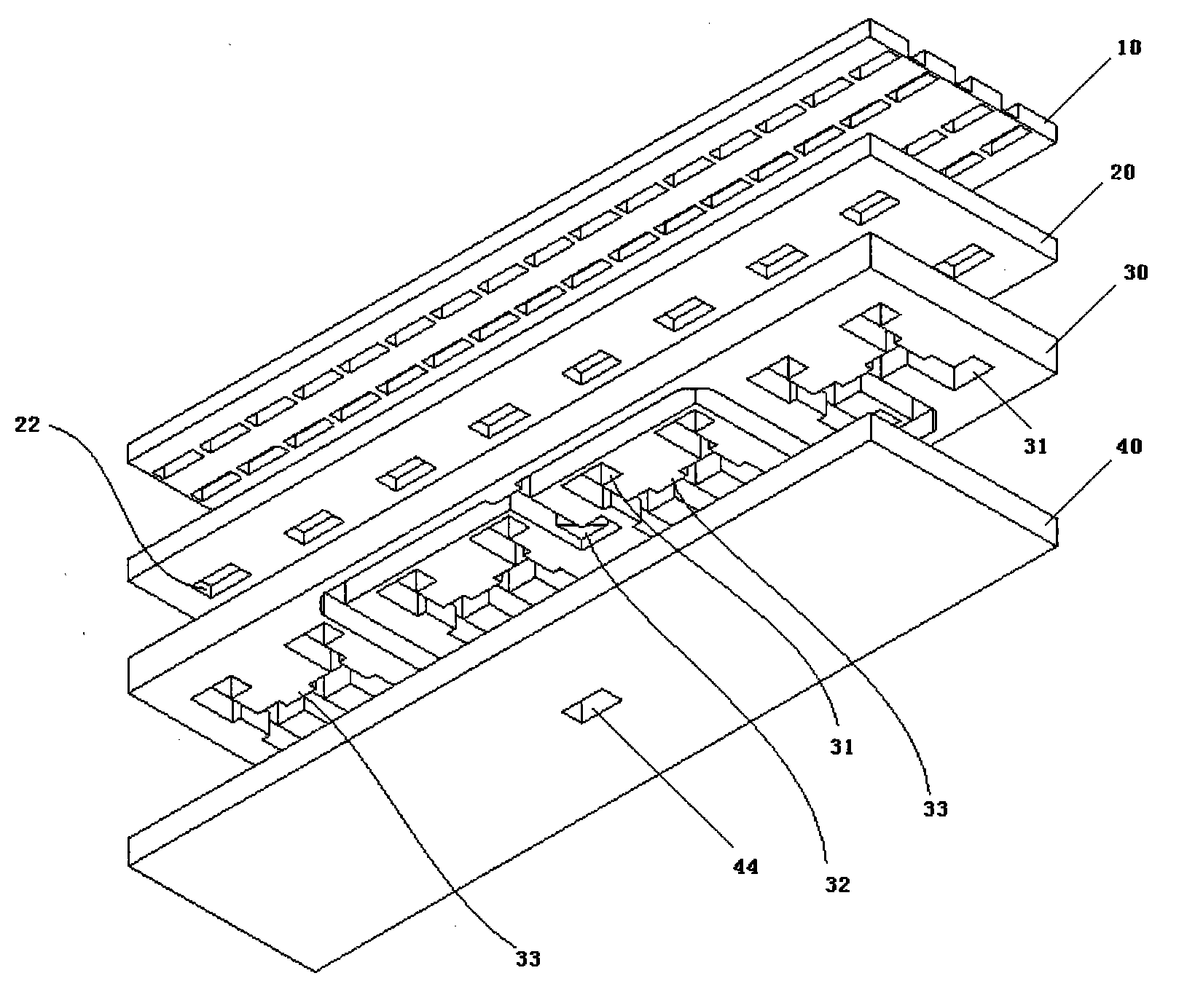
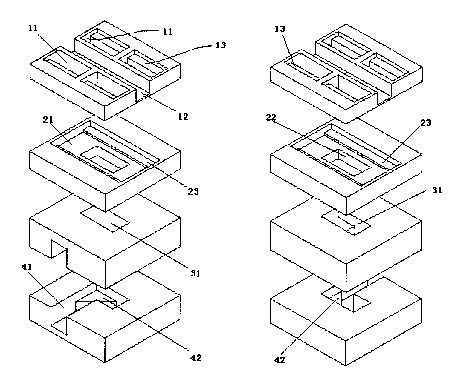
[0026] Such as figure 1 , 2 The shown antenna is composed of four layers, which are the radiation layer 10, the rectangular exciting cavity layer 20, the upper layer 30 of the waveguide E-T feeding network, and the lower layer 40 of the waveguide E-T feeding network. The four-layer structure is stacked together in order to form a flat panel antenna. The input and output waveguide port 44 located in the middle of the lower layer 40 of the waveguide E-T feeding network is the final input and output port of the signal.

[0027] Several rectangular opening waveguides 11 on the radiation layer 10 complete the conversion of the radio frequency signal from the circuit to the free space. Compared with various shapes of microstrip patches (rectangular, circular, elliptical, etc.), oscillators, slots, etc., which work on resonance characteristics, the rectangular opening waveguide 11 has high-pass characteristics, so the operating bandwidth is large. Rectangular opening waveguides 11 ...


PUM


Abstract

The invention provides a waveguide flat array antenna, which has the characteristics of broadband and high-efficiency feed. Rectangular open waveguides 11 are used as radiation units; four rectangular open waveguides in one group form a sub array, and are arranged in a 2*2 rectangle and supplied with broadband equal-amplitude in-phase feed by a rectangular cavity 21; and in order to ensure efficient transmission of electromagnetic wave, the joint of each rectangular open waveguide 11 and the rectangular cavity 21 is provided with matched steps 13 and 23. The center of the rectangular cavity 21 is provided with a rectangular window 22 which is connected with a feed network of the next layer. In order to ensure smooth signals, a rectangular matching block 42 is arranged at the feed network corner connected with each rectangular window 22. The feed network consists of multistage parallel E-T so as to ensure that the antenna has enough bandwidth. The transceiving capacity of circularly polarized wave is realized by arranging a circularly polarized cover. Compared with the conventional flat antenna, the waveguide flat array antenna has broader bandwidth and higher feed efficiency.

Description

technical field [0001] The invention relates to a waveguide plate array antenna, which has the advantages of wide working frequency band and high efficiency. After installing the circular polarization cover 1, the circular polarization receiving and transmitting characteristics can also be realized. Background technique [0002] Antenna gain and bandwidth are very important indicators in communication, radar and other systems. The microstrip panel antenna generally forms a feeding network by microstrip, stripline, etc., and the radiation unit usually chooses a microstrip patch, a slot, etc., and the panel antenna composed of a dielectric material, when the frequency increases (especially X~Ka Band), the feed loss increases rapidly, seriously affecting the gain. There are two types of waveguide slot arrays: standing wave arrays and traveling wave arrays. Compared with microstrip antennas using printing technology, their manufacturing costs are high. Usually requires a weld...

Claims


Application Information

Patent Timeline
Patent Type & Authority Applications(China)
IPC IPC(8): H01Q1/36H01Q1/52H01Q13/06H01Q15/24H01Q21/00
Inventor 李峰
Owner 李峰
Why Eureka
Try Eureka