Rectangular waveguide-microstrip power divider and rectangular waveguide matching load

A technology of power divider and rectangular waveguide, which is applied in the direction of waveguide devices, electrical components, connecting devices, etc., can solve the problem that the matching load of rectangular waveguide cannot meet the requirements of compact system, achieve simple and mature processing and assembly technology, and expand standing wave bandwidth , the effect of compact structure

Active Publication Date: 2019-05-28
NORTHWEST INST OF NUCLEAR TECH
View PDF4 Cites 5 Cited by
  • Summary
  • Abstract
  • Description
  • Claims
  • Application Information

AI Technical Summary

Problems solved by technology

[0003] In order to solve the technical problem that the existing rectangular waveguide matching load cannot meet the requirements of a compact system, the present invention provides a rectangular waveguide-microstrip power divider, and a thin film power resistor is connected to the microstrip port of the power divider to form a rectangular waveguide matching The load can achieve a relatively wide matching bandwidth within a short longitudinal length (one-tenth of the waveguide wavelength), which is much smaller than the longitudinal length of the traditional rectangular waveguide matching load

Method used


Image

  • Rectangular waveguide-microstrip power divider and rectangular waveguide matching load
  • Rectangular waveguide-microstrip power divider and rectangular waveguide matching load
  • Rectangular waveguide-microstrip power divider and rectangular waveguide matching load

Examples


Embodiment 1

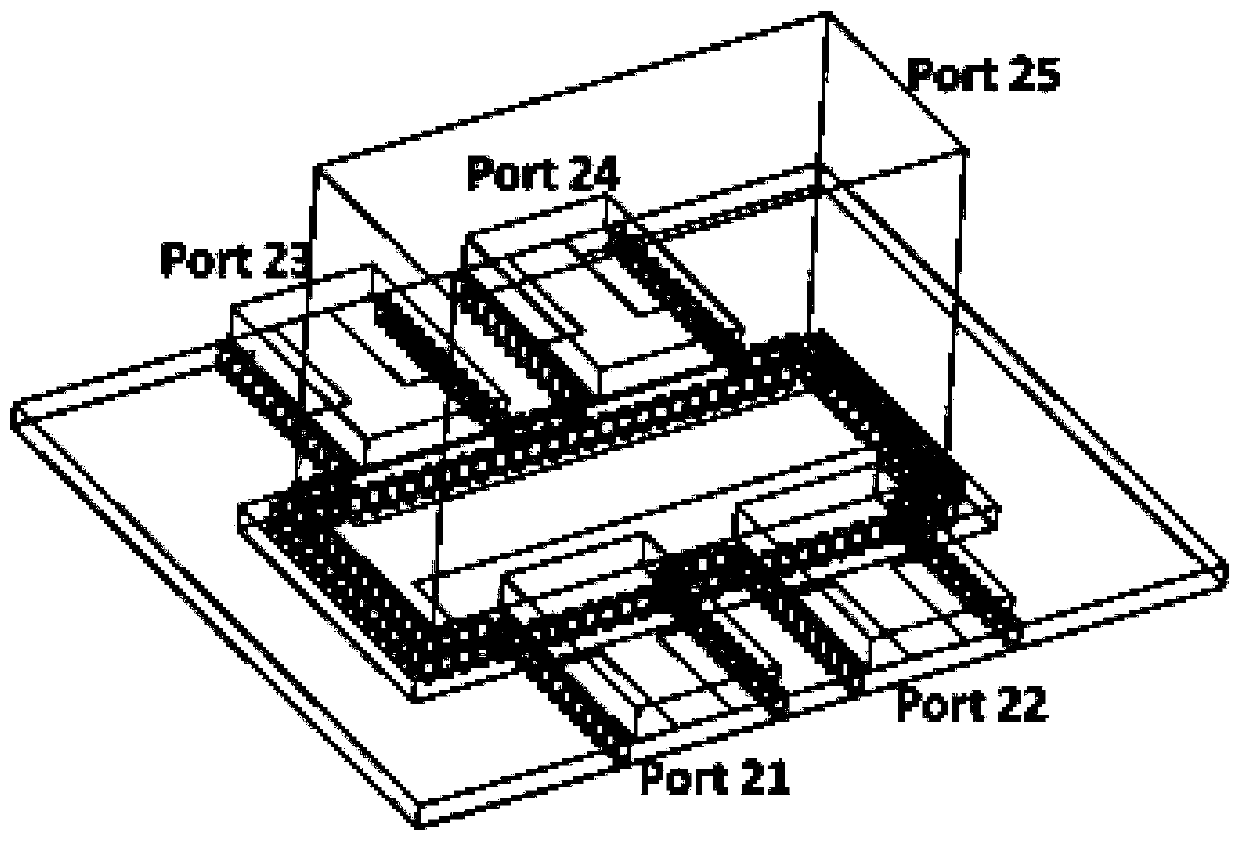
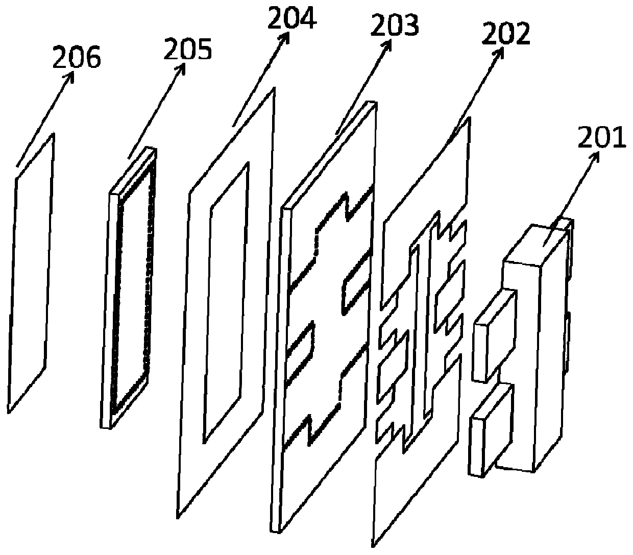
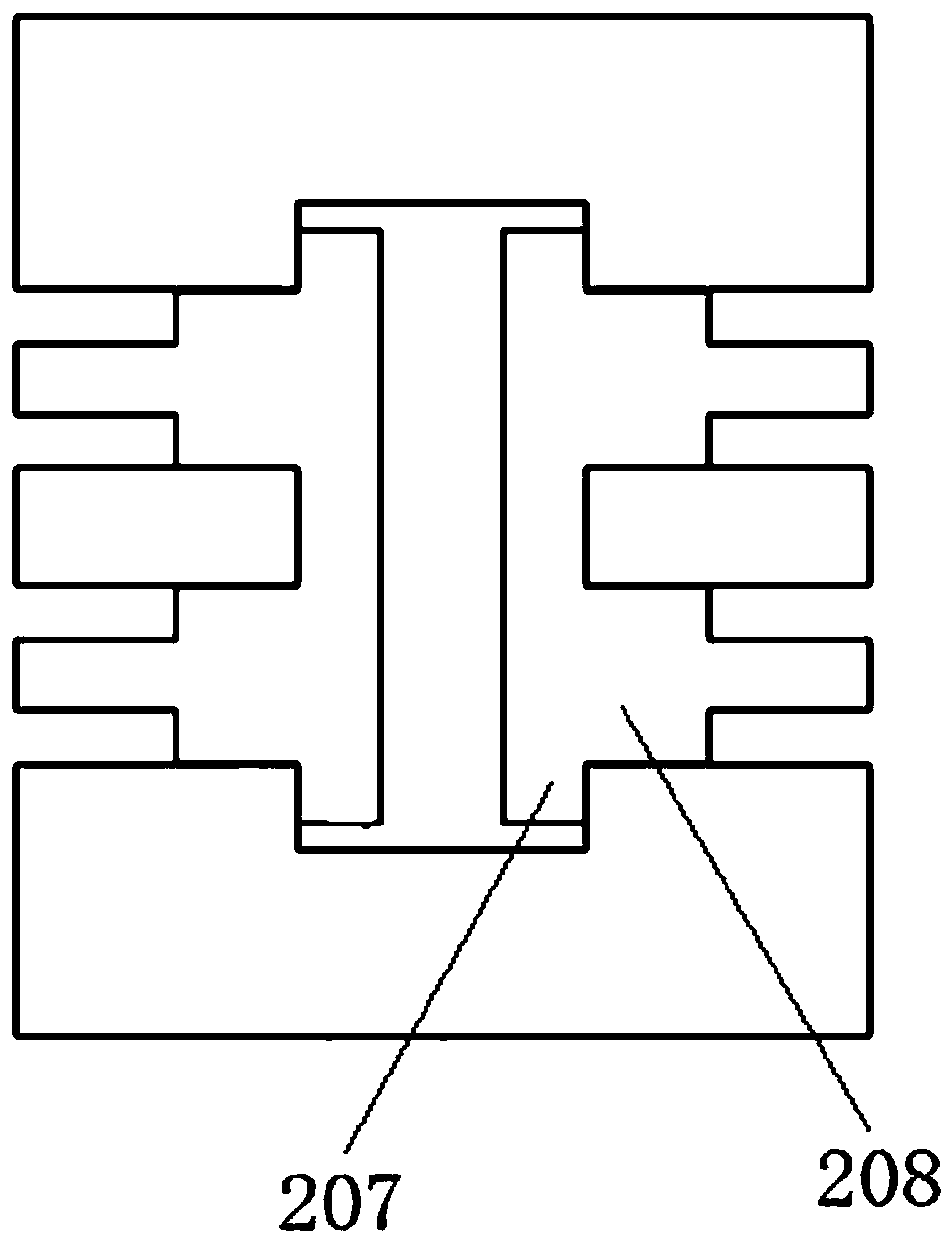
[0051] Such as figure 1 , figure 2 , image 3As shown, it is a rectangular waveguide-microstrip four-way power divider, which has a rectangular waveguide input port port25 and four microstrip output ports port 21-port 24; the compact waveguide-microstrip four-way power divider includes sequentially stacked The input rectangular waveguide 201 , the first metal layer 202 , the first dielectric layer 203 , the second metal layer 204 , the second dielectric layer 205 and the third metal layer 206 are set. Wherein, the microstrip coupling probe 207, the microstrip impedance transition section 208 and the microstrip output ports port 21-port 24 are all arranged on the first metal layer 202, the second metal layer 204 constitutes the microstrip ground plane, and the first dielectric layer 203 and the second dielectric layer 205 are provided with a plurality of through holes 2031, 2051, these through holes are surrounded by a geometric figure, these through holes can limit the elec...

Embodiment 2

[0056] In order to further improve the matching bandwidth of the rectangular waveguide port, in this embodiment Figure 1-3 Based on the shown rectangular waveguide-microstrip four-way power divider, a rectangular waveguide-microstrip six-way power divider is proposed.

[0057] Such as Figure 4 , Figure 5 , Figure 6 As shown, the six-way power divider has a rectangular waveguide input port port45, four microstrip output ports port41-port44 and two coplanar waveguide output ports port46-port47. The six-way power divider includes an input rectangular waveguide 401, a first metal layer 402, a first dielectric layer 403, a second metal layer 404, a second dielectric layer 405, a third metal layer 406, a third dielectric layer 407 and The fourth metal layer 408 . Wherein, the microstrip output ports port41-port44, the microstrip coupling probe 409, and the microstrip impedance transition section 410 are all arranged on the first metal layer 402, the second metal layer 404 co...

example

[0065] Taking the X-band four-way and six-way power splitters as an example, the rectangular input waveguide size is 22.86×10.16mm, the dielectric layer is made of Rogers 5880 dielectric board with a dielectric constant of 2.2, and the loss tangent of the dielectric layer is 0.009 . All output ports of the four-way and six-way power splitters have an impedance of 50 ohms.

[0066] According to the invention Figure 7 and 8 Dimensions in the X-band four-way power divider are: w 1 =2.48,w 2 =6.30, w 3 =20.94,a=36,a 0 =22.86,a 1 =26,b=30,b 0 =10.16,b 1 =13,d 1 =2.16,d 2 =4.28,d 3 =4.14, h 1 =1.016, h 2 =1.5,L s =1.016,L p =0.8, r 0 = 0.25. The size of the X-band six-way power splitter is: w 1 =2.48,w 2 =6.30, w 3 =20.94,w 4 =1.51,w s =8.53,a=36,a 0 =22.86,a 1 =26,b=30,b 0 =10.16,b 1 =13,d 1 =2.16,d 2 =4.05,d 3 =4.14,d s =2.95,h 1 =1.016, h 2 =1.5, h 3 =1.016, L s =0.508, L s1 =2.60,L p =0.8, r 0 =0.25,w f =2.54. The above numerical units are...


PUM


Abstract

In order to solve the technical problem that an existing rectangular waveguide matching load cannot meet the requirement of a compact system, the invention provides a rectangular waveguide-microstrippower divider and a rectangular waveguide matching load. The rectangular waveguide-microstrip power divider comprises an input rectangular waveguide, a first metal layer, a first dielectric layer, a second metal layer, a second dielectric layer and a third metal layer which are stacked sequentially. A micro-strip coupling probe and four micro-strip output ports are arranged on the first metal layer. The second metal layer forms a microstrip ground plane. Through holes are formed in the first dielectric layer and the second dielectric layer. E faces of the four micro-strip output ports are coupled to the side wall of the wide edge of the input rectangular waveguide and are orthogonal to the input rectangular waveguide by 90 degrees, and the E faces of the four micro-strip output ports are distributed on the two sides of the wide edge of the input rectangular waveguide in pairs. The micro-strip output ports located on the same side of the wide edge of the input rectangular waveguide share one micro-strip coupling probe to couple energy outwards from the input rectangular waveguide. The rectangular waveguide-microstrip power divider is symmetrical along the E surface and the H surfaceof the input rectangular waveguide.

Description

technical field [0001] The invention relates to a rectangular waveguide-microstrip power divider and a rectangular waveguide matching load formed by the power divider. Background technique [0002] Rectangular waveguide matching loads are widely used in microwave circuits and systems to reduce standing waves, absorb excess energy, and improve system stability. In order to achieve a good matching bandwidth, the length of the absorber in the rectangular waveguide matching load is generally not less than half of the guided wave wavelength. However, in most cases, the length of the absorber is greater than one guided wave wavelength, which cannot meet the requirements of a compact system. Contents of the invention [0003] In order to solve the technical problem that the existing rectangular waveguide matching load cannot meet the requirements of a compact system, the present invention provides a rectangular waveguide-microstrip power divider, and a thin film power resistor is...

Claims


Application Information

Patent Timeline
Patent Type & Authority Applications(China)
IPC IPC(8): H01P5/12H01P1/26
Inventor 郭乐田黄文华邵浩谢少毅李佳伟巴涛张余川
Owner NORTHWEST INST OF NUCLEAR TECH
Why Eureka
Try Eureka