Mechanical equipment bottom damping device

A technology of shock absorbing device and mechanical equipment, applied in the direction of mechanical equipment, shock absorber, spring/shock absorber, etc., can solve the problems of affecting the working efficiency of mechanical equipment, not obvious shock absorbing effect, heavy operation of the device, etc. Better shock absorption, innovative structural design, and harm reduction effect

Inactive Publication Date: 2018-08-17
汤以骋
View PDF0 Cites 9 Cited by
  • Summary
  • Abstract
  • Description
  • Claims
  • Application Information

AI Technical Summary

Problems solved by technology

[0002] With the advancement of science and technology, large and small factories, large-scale machinery and equipment can be seen everywhere to supply the production of materials, and these large-scale machinery and equipment will inevitably produce vibrations during the production process. It is this vibration that affects the products and staff. brought great harm, but the existing shock absorbing device can not solve the shock absorbing problem well, often the device is heavy and inconvenient to operate, and only a simple single layer shock absorbing can not meet the production demand well, and The shock absorption effect is not very obvious, which seriously affects the working efficiency of the mechanical equipment. A single shock absorption mechanism cannot better achieve the shock absorption effect. Therefore, a shock absorption device at the bottom of the mechanical equipment is proposed

Method used


Image

  • Mechanical equipment bottom damping device
  • Mechanical equipment bottom damping device
  • Mechanical equipment bottom damping device

Examples


Embodiment Construction

[0016] The following will clearly and completely describe the technical solutions in the embodiments of the present invention with reference to the accompanying drawings in the embodiments of the present invention. Obviously, the described embodiments are only some, not all, embodiments of the present invention. Based on the embodiments of the present invention, all other embodiments obtained by persons of ordinary skill in the art without making creative efforts belong to the protection scope of the present invention.

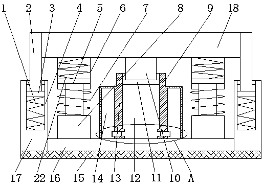
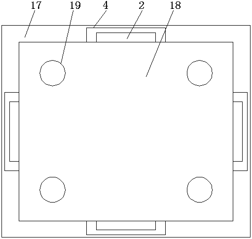
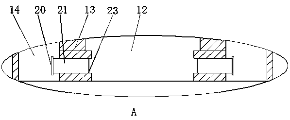
[0017] see Figure 1~3 , in an embodiment of the present invention, a shock absorbing device at the bottom of mechanical equipment includes a first spring 1, a support plate 2, a bottom plate 3, a rectangular groove 4, a push rod 5, a fixing box 6, a return spring 7, a base 8, an air pressure reducing Vibration device 9, middle plate 10, baffle plate 11, booster chamber 12, frame 13, pressure delivery chamber 14, damping layer 15, bottom pad 16, side plate 17,...


PUM


Abstract

The invention discloses a mechanical equipment bottom damping device which comprises a first spring, a supporting plate, a bottom plate, a rectangular channel, a push rod, a fixing box, a reset spring, a base, an air pressure damping device, a middle plate, a baffle, a supercharge bin, a rack, pressure conveying bins, a damping layer, a bottom cushion, side plates, a top plate, a threaded hole, astopping ring, a connecting pin, a second spring and a through hole. The side plates are fixedly connected to the periphery of the bottom cushion, the side plates are of a rectangular frame structure,the top plate is arranged above the bottom cushion, the middle portion of the part between the top plate and the bottom cushion is provided with a hydraulic damping device, the air pressure damping device is composed of the middle plate, the baffle, the supercharge bin, the rack, the pressure conveying bins, the stopping ring, the connecting pin and the through hole, the middle plate is fixedly connected to the middle portion of the bottom of the top plate, the baffle is arranged below the middle plate, the rack is arranged at the middle portion of the top face of the bottom cushion, the supercharge bin is arranged at the center position of the interior of the rack, and the pressure conveying bin are arranged around the supercharge bin.

Description

technical field [0001] The invention relates to the field of shock absorbing equipment, in particular to a shock absorbing device at the bottom of mechanical equipment. Background technique [0002] With the advancement of science and technology, large and small factories, large-scale machinery and equipment can be seen everywhere to supply the production of materials, and these large-scale machinery and equipment will inevitably produce vibrations during the production process. It is this vibration that affects the products and staff. brought great harm, but the existing shock absorbing device can not solve the problem of shock absorption well, often the device is heavy and inconvenient to operate, and only a simple single-layer shock absorption can not meet the production needs well, and The damping effect is not very obvious, which seriously affects the working efficiency of the mechanical equipment. A single damping mechanism cannot better achieve the damping effect. The...

Claims


Application Information

Patent Timeline
Patent Type & Authority Applications(China)
IPC IPC(8): F16F7/00F16F15/023F16F15/06
CPCF16F7/00F16F15/023F16F15/06
Inventor 汤以骋
Owner 汤以骋
Why Eureka
Try Eureka