Screw power machine mechanical seal device

A technology of mechanical sealing device and power machine, which is applied in the direction of engine sealing, mechanical equipment, engine components, etc. It can solve the problems of keeping the end face on a plane for a long time, twisting and tearing of the static ring bellows, and difficult disassembly of the gland , to achieve the effect of solving the problem of different expansion coefficients, good structural stability and reliable use

Active Publication Date: 2016-01-20
丹东隆强科技有限责任公司
View PDF5 Cites 0 Cited by
  • Summary
  • Abstract
  • Description
  • Claims
  • Application Information

AI Technical Summary

Problems solved by technology

[0003]The mechanical seal is the key component and the only vulnerable part of the screw power machine. Its quality directly affects the popularization and application, service life and maintenance cycle of the equipment, and the seal fails Finally, the medium or cooling water will enter the bearing gear chamber on the rear side of the mechanical seal device, resulting in emulsification of the lubricating oil, which seriously affects the lubrication of the bearings and gears
[0004] CN101825181A vapor-liquid full-flow screw power machine mechanical seal device applied by the applicant discloses an improved screw power machine shaft mechanical seal device, which is an axial double-end surface And the radial double-end mechanical seal mechanism device, the screw power machine shaft mechanical seal device still has deficiencies: First, due to the frequent start and stop of the equipment, and due to the large shaft diameter and large torque, it is easy to cause the static ring bellows to twist , tearing, resulting in failure of the mechanical seal; the second is that the moving ring has an O-ring groove on one side of the moving ring, so that the matching surface between the moving ring and the shaft sleeve is narrow, and the O-ring groove and the other side are connected to the shaft. The anti-rotation pin hole structure matched with the sleeve will easily lead to increased stress on the moving ring, deformation, and increased leakage; third, the radial double-end static ring is formed by processing two end faces on an integral ring, that is, one-piece The radial double-end static ring has a non-independent compensation structure on its two friction end faces. Since the diameters of the two end faces and the media blocked respectively are different, the amount of wear is different, and the two end faces cannot be kept on the same plane for a long time, resulting in leakage. 4. The gland of the mechanical seal and the body are fixed by the circlip, and the circlip and its fixing groove are in clearance fit, resulting in poor fixing stability of the gland and affecting the cooperation between the static ring and the moving ring, resulting in Increased leakage and difficult removal of the gland

Method used


Image

  • Screw power machine mechanical seal device
  • Screw power machine mechanical seal device
  • Screw power machine mechanical seal device

Examples


Embodiment Construction

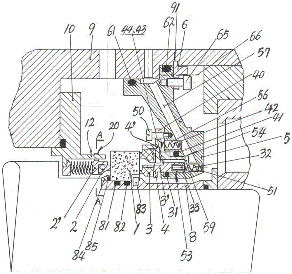
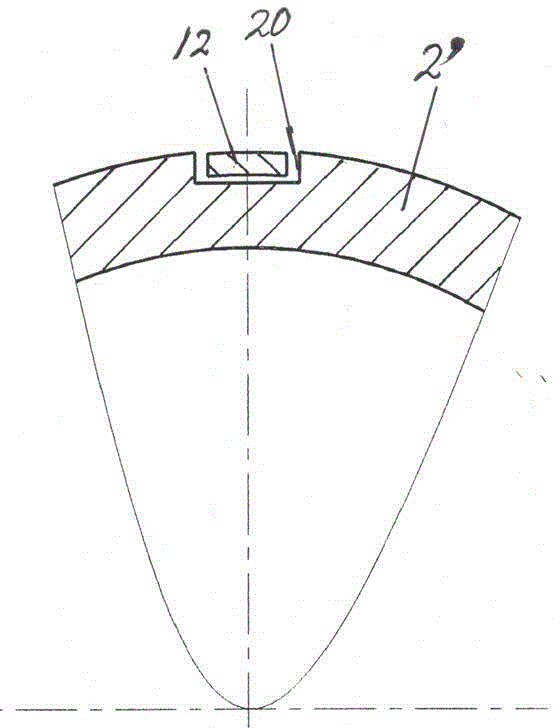
[0015] Screw power machine of the present invention The mechanical seal device consists of the moving ring 1 fixedly installed on the rotor shaft sleeve 8, the metal bellows respectively arranged on the left side of the moving ring 1 to compensate the static ring 2 and the spring on the right side to compensate the inner static ring 3 and the outer static ring 4 , The static ring seat 5 is formed to form an axial double-end face and a radial double-end mechanical seal mechanism. The metal bellows compensating static ring 2 is fixedly connected with the mouth of the body 9 through its connecting seat 10, and the ring 2' of the bellows compensating static ring 2 and its connecting seat 10 are respectively provided with mutually matching card slots 20 and The bump 12 prevents the bellows from compensating the excessive torsion of the front end of the static ring 2; the moving ring 1 is installed in cooperation with the spigot of the shaft sleeve 8, and two auxiliary sealing ring...


PUM


Abstract

Screw power machine of the present invention The mechanical seal device consists of a moving ring (1) fixedly installed on the rotor shaft sleeve (8), a metal bellows compensation static ring (2) respectively arranged on the left side of the moving ring (1), and a spring compensation diameter on the right side. The inward static ring (3) and the outer static ring (4) are composed of double static rings and a static ring seat (5), forming an axial double-end face and a radial double-end mechanical seal mechanism. Simple structure, reliable use, good stability, convenient loading and unloading.

Description

technical field [0001] The present invention relates to a mechanical device converted into power by pressurized steam or liquid or a vapor-liquid mixed medium, that is, a vapor-liquid full-flow screw power machine, especially its mechanical seal device. Background technique [0002] The vapor-liquid full-flow screw power machine consists of a casing, a pair of screw rotors that rotate and cooperate with each other, a mechanical seal, a synchronous gear, a low-pressure end seat, and a high-pressure end seat. Synchronous gears, bearings, and mechanical seals are respectively installed in low-pressure end seats and high-pressure end seats, and steam inlet and outlet pipes are respectively opened at both ends of the casing. High-pressure steam enters from the steam inlet, acts on the rotation of the helical rotor, and then discharges from the steam outlet, converting the medium pressure into power output. [0003] The mechanical seal is the key component and the only vulnerable...

Claims


Application Information

Patent Timeline
Patent Type & Authority Patents(China)
IPC IPC(8): F16J15/16F16J15/50
Inventor 李继明王国春何德贵
Owner 丹东隆强科技有限责任公司
Why Eureka
Try Eureka