Supercharge Your Innovation With Domain-Expert AI Agents!

Bonding device

一种焊接装置、焊接工具的技术,应用在焊接设备、非电焊设备、电气元件等方向,能够解决维修保养化费时间、不能检测毛细管前端振动变化、焊接性能影响等问题,达到简单构成的效果

Active Publication Date: 2011-05-25
SHINKAWA CO LTD
View PDF2 Cites 5 Cited by
  • Summary
  • Abstract
  • Description
  • Claims
  • Application Information

AI Technical Summary

Problems solved by technology

However, in the conventional techniques described in Patent Documents 1 and 2, although changes in the ultrasonic output of the ultrasonic mold itself can be detected, changes in the vibration of the tip of the capillary, which is very small compared to the vibration of the entire ultrasonic mold, cannot be detected.
[0010] In addition, both of the conventional technologies described in Patent Documents 1 and 2 install the load sensor on the position where the ultrasonic vibration amplitude is generated in the ultrasonic mold. The problem that the sensor affects the welding performance
In addition, the sensor needs to be replaced when the ultrasonic mold is replaced. Whenever the ultrasonic mold is replaced, calibration needs to be adjusted, etc., and there is a problem of time-consuming maintenance.

Method used


Image

  • Bonding device
  • Bonding device
  • Bonding device

Examples


Embodiment Construction

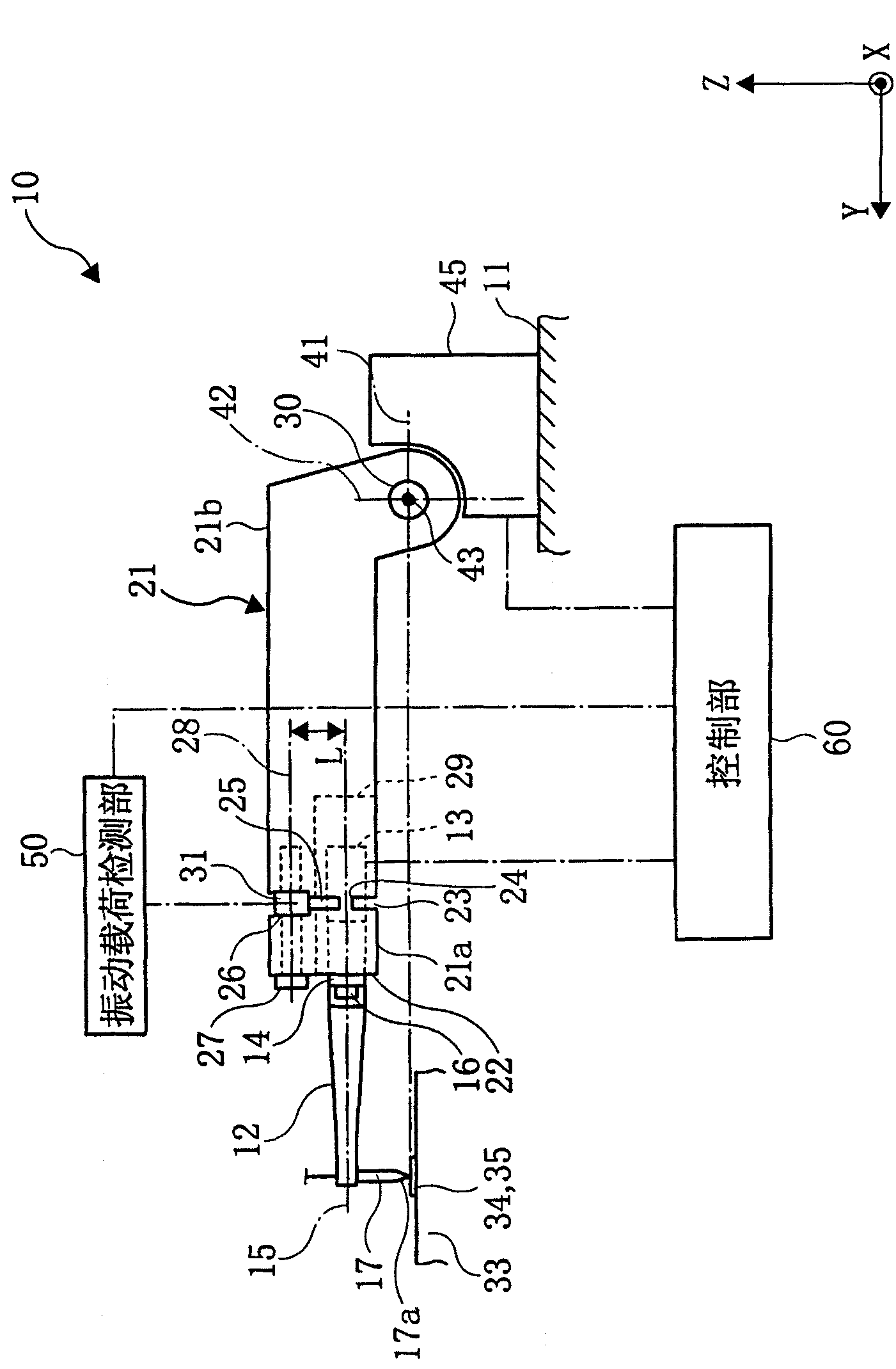
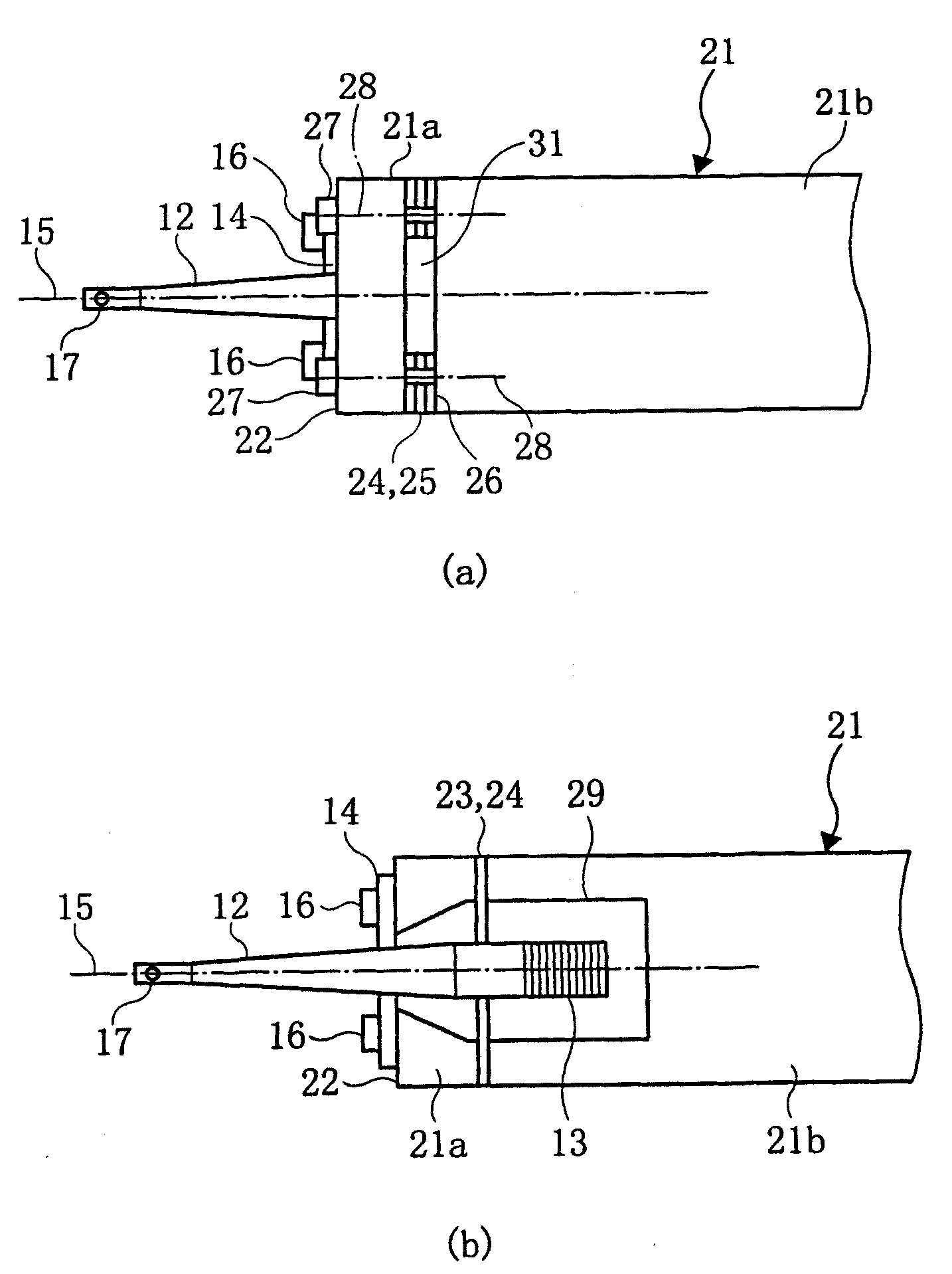
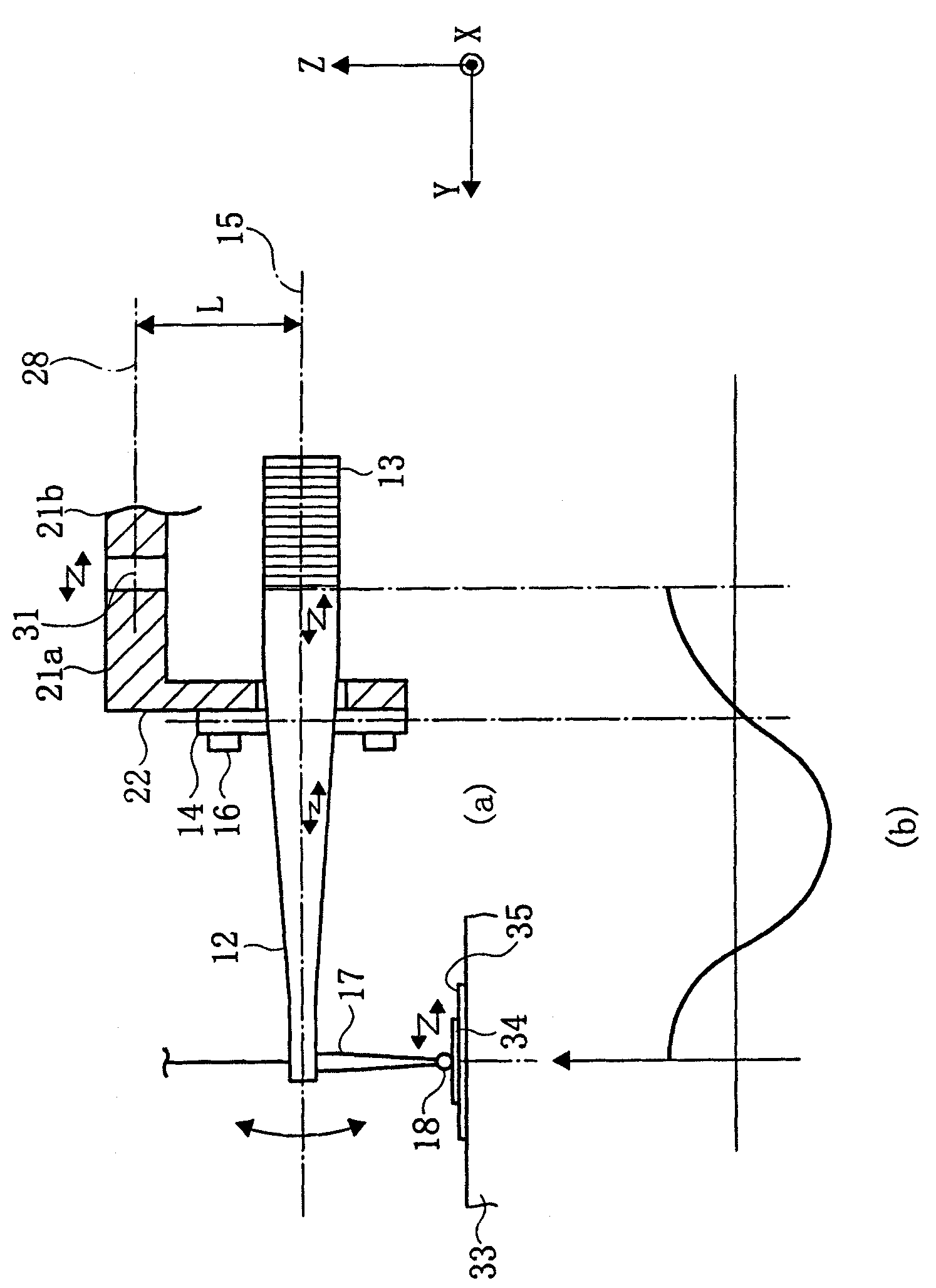
[0062] Preferred embodiments of the present invention will be described below with reference to the accompanying drawings. Such as figure 1 As shown, the wire bonding device 10 of this embodiment includes a bonding head 11 as a base, an ultrasonic vibrator 13, an ultrasonic mold 12, a capillary 17 as a bonding tool, a flange 14 provided on the ultrasonic mold 12, a welding arm 21, and a load. The sensor 31 , the drive motor 45 , the vibration load detection unit 50 , the control unit 60 , and the soldering table 33 that absorb and fix the semiconductor chip 34 and the substrate 35 to be soldered.

[0063] A driving motor 45 for driving the welding arm 21 to rotate is provided on the welding head 11 . The ultrasonic vibrator 13 is formed by stacking a plurality of piezoelectric elements, and is mounted on the rear end side of the ultrasonic mold 12 . Also, a capillary 17 is attached to the tip of the ultrasonic mold 12 . The flange 14 is provided at a position to be a vibrat...


PUM


Abstract

A bonding device comprises an ultrasonic horn (12) which longitudinally oscillates in the direction of the central axis (15) by resonating to the oscillation of an ultrasonic oscillator (13), a capillary (17) fixed to the antinode of oscillation of the ultrasonic horn (12), a flange (14) provided at the node of oscillation of the ultrasonic horn (12), a bonding arm (21), a load sensor (31) fixed between the rotation center (43) of the bonding arm (21) and the flange fixing surface (22), and an oscillation load detecting section (50) for detecting the oscillation load, which is in the direction of the central axis (15) of the ultrasonic horn (12) and applied to the distal end (17a) of the capillary (17) by extracting a signal in a frequency band near the oscillation frequency of the ultrasonic oscillator from a signal acquired by the load sensor (31) through a band-pass filter. With such an arrangement, the oscillation load applied to the tip of the bonding tool is detected by a simplearrangement in the bonding device.

Description

technical field [0001] The invention relates to the structure of a welding device. Background technique [0002] In the manufacturing process of a semiconductor device, a wire bonding apparatus for connecting a pad as an electrode of a semiconductor chip and a lead as an electrode of a lead frame with a wire of a thin metal wire is often used. Most of the wire welding devices are equipped with a welding arm driven by a drive motor, an ultrasonic mold (horn) installed on the welding arm, a capillary installed on the front end of the ultrasonic mold, and an ultrasonic vibrator installed on the ultrasonic mold to drive the welding arm to rotate, so that the capillary Relative to the welding point or the pin moves along the direction of connection and separation, the initial ball formed at the front end of the capillary is pressure-welded to the welding point, and the lead wire is pressure-welded to the pin. At the same time, the ultrasonic vibrator makes the ultrasonic mold res...

Claims


Application Information

Patent Timeline
Patent Type & Authority Applications(China)
IPC IPC(8): H01L21/60H01L21/607
CPCH01L2224/85205B23K2201/42H01L2924/01082H01L2224/78301H01L2924/00014H01L2924/01004H01L24/85H01L2224/789H01L2924/01005H01L2924/01033H01L2924/01006H01L24/78B23K20/007H01L2924/014H01L2224/85206H01L2224/451B23K2101/42H01L2224/48H01L2924/00H01L2224/45099H01L2224/05599
Inventor 青柳伸幸濑山耕平
Owner SHINKAWA CO LTD
Features
  • R&D
  • Intellectual Property
  • Life Sciences
  • Materials
  • Tech Scout
  • Unparalleled Data Quality
  • Higher Quality Content
  • 60% Fewer Hallucinations
Learn More