Direct current (DC) travelling wave fault location method based on wave velocity optimization

A technology of fault distance measurement and fault distance, which is applied in the direction of fault location, etc., can solve the problems of large influence of transition resistance on distance measurement results, large distance measurement error, unacceptability, etc., to eliminate line dispersion effect and improve distance measurement accuracy Effect

Active Publication Date: 2011-06-08
EXAMING & EXPERIMENTAL CENT OF ULTRAHIGH VOLTAGE POWER TRANSMISSION COMPANY CHINA SOUTHEN POWER GRID
View PDF4 Cites 26 Cited by
  • Summary
  • Abstract
  • Description
  • Claims
  • Application Information

AI Technical Summary

Problems solved by technology

[0010] The purpose of the present invention is to provide a DC traveling wave fault location method based on wave velocity optimization, which aims to solve the problem that the existing fa

Method used


Image

  • Direct current (DC) travelling wave fault location method based on wave velocity optimization
  • Direct current (DC) travelling wave fault location method based on wave velocity optimization
  • Direct current (DC) travelling wave fault location method based on wave velocity optimization

Examples


Embodiment Construction

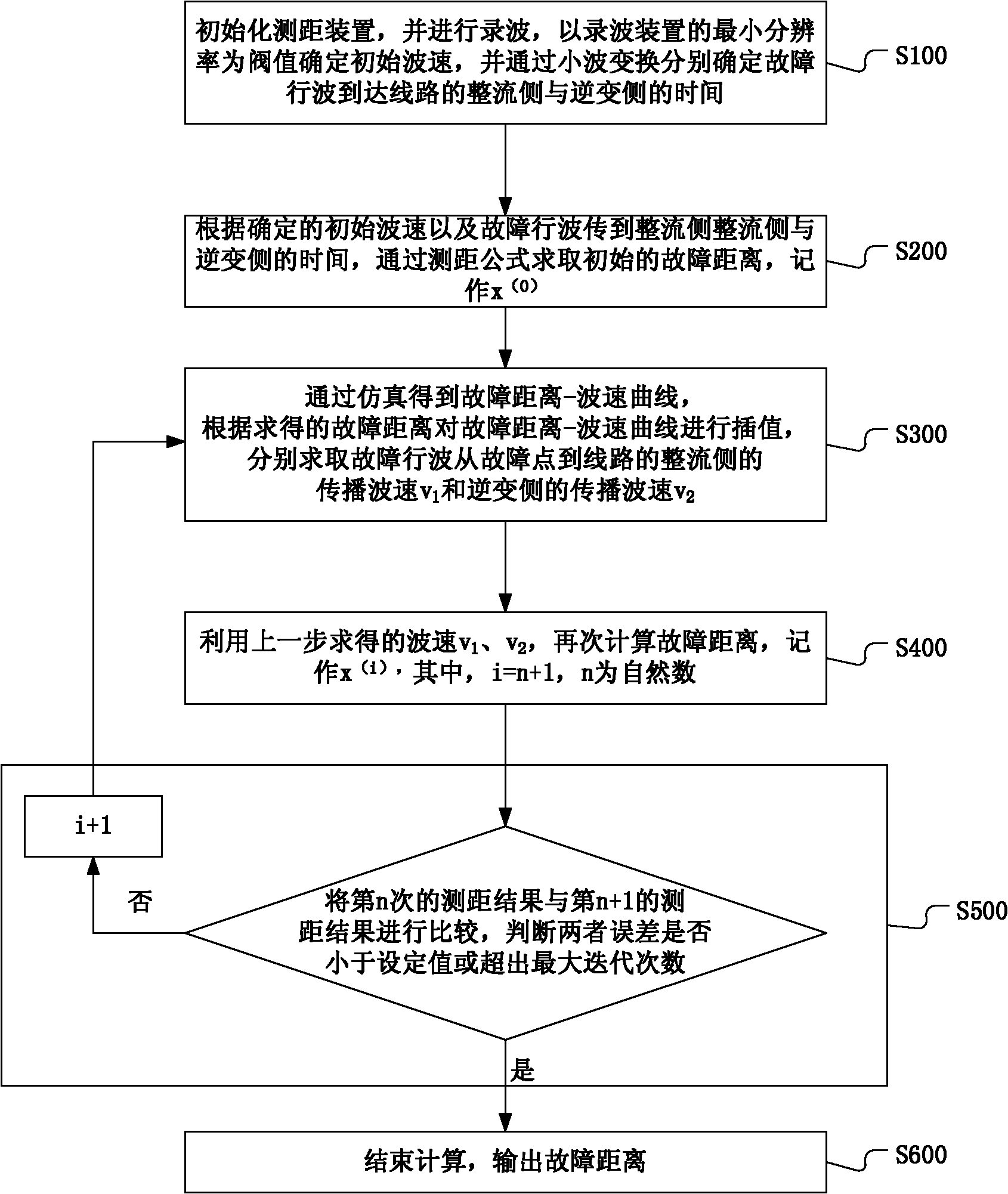
[0039] In order to make the object, technical solution and advantages of the present invention more clear and definite, the present invention will be further described in detail below with reference to the accompanying drawings and examples.

[0040] In order to enable the successful implementation of the DC traveling wave fault location method based on wave velocity optimization under the broadband system provided by the present invention, this embodiment firstly provides a method for coordinating wave head detection and wave velocity selection under the broadband system, aiming at reducing or even Eliminate the influence of transition resistance on ranging results.

[0041] Because the initial fault traveling wave is a step wave, it contains all components from zero frequency to infinite frequency. Due to the dispersion effect, different frequency components have different propagation speeds in the DC line. After a period of transmission, the phase relationship between the f...


PUM


Abstract

The invention discloses a direct current (DC) travelling wave fault location method based on wave velocity optimization, which comprises the following steps: obtaining the fault distance via a ranging formula according to the determined initial wave velocity and the time of transferring the fault travelling wave to a rectification side and an inversion side, and marking the fault distance as x (0); performing interpolation of a fault distance-wave velocity curve according to the obtained fault distance, and obtaining a wave velocity v1 of transmitting the fault travelling wave from the fault point to the rectification side of a line and a wave velocity v2 of transmitting the fault travelling wave from the fault point to the inversion side of the line respectively; calculating the fault distance again by use of the obtained wave velocities v1 and v2, and marking the fault distance as x (i); comparing the nth ranging result and the (n+1)th ranging result, and judging whether the error of the two is less than a set value or greater than the maximum iteration times; if the error is less than the set value or greater than the maximum iteration times, outputting the fault distance; and if the error is greater than the set value, performing iteration again by use of x (i) and circulating to calculate the fault distance. By adopting the method disclosed by the invention, the travelling wave fault location precision of a DC line can be greatly improved in the premise of not changing the hardware facility of the existing ranging device.

Description

technical field [0001] The present invention relates to a fault location method, in particular to a direct current traveling wave fault location method based on wave velocity optimization. Background technique [0002] Traveling wave fault location is a fault location method based on the transmission theory of traveling waves on the line. When a fault occurs on a transmission line, traveling waves of current and voltage will be generated to both ends of the line at a speed close to the speed of light. By analyzing the fault point information contained in the fault traveling wave, the fault distance can be calculated by using the transmission time of the fault traveling wave. Taking the traditional two-terminal traveling wave ranging as an example, this method mainly detects the transmission time difference between the fault wave head and the two ends of the line, and uses the following formula to calculate the distance measurement result: [0003] X=(L+Δt·v) / 2 [0004] Amo...

Claims


Application Information

Patent Timeline
IPC IPC(8): G01R31/08
Inventor 张怿宁蔡泽祥郭波张楠
Owner EXAMING & EXPERIMENTAL CENT OF ULTRAHIGH VOLTAGE POWER TRANSMISSION COMPANY CHINA SOUTHEN POWER GRID
Why Eureka
Try Eureka