Pressed cage, self-aligning roller bearing, and method of manufacturing pressed cage

A manufacturing method and cage technology, applied in the direction of roller bearings, rolling contact bearings, rotating bearings, etc., can solve problems such as the deviation of the bending degree of the connection part, and achieve the effect of excellent precision

Inactive Publication Date: 2011-06-15
NTN CORP
View PDF14 Cites 12 Cited by
  • Summary
  • Abstract
  • Description
  • Claims
  • Application Information

AI Technical Summary

Problems solved by technology

One end portion of the peripheral wall is the part that is finally formed into the flange 105. However, since there is variation in the degree of curvature at each connecting portion, it is difficult to make the flatness of the two plate surfaces uniform over the entire circumference in the circumferential direction. Form the bending angle into a uniform bending angle over the entire circumference
For this reason, it is difficult to use the flange to form the structural parts requiring precision throughout the circumferential direction or at uniform intervals in the circumferential direction.

Method used


Image

  • Pressed cage, self-aligning roller bearing, and method of manufacturing pressed cage
  • Pressed cage, self-aligning roller bearing, and method of manufacturing pressed cage
  • Pressed cage, self-aligning roller bearing, and method of manufacturing pressed cage

Examples


reference example 1

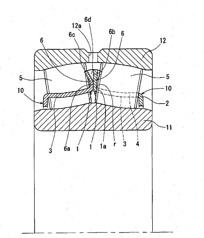
[0160] In the stamped cage according to Reference Example 1, bottom expansion was not performed. The above-mentioned pressed cage can be arranged concentrically with the inner ring 431 so that each pocket 423 is located on the raceway surface 432 of the inner ring 431 . By pressing the rollers 421 into the pockets 423 with each pocket 423 disposed on the raceway surface 432, the flange 424 pressed by one end surface of the roller 421 falls so that the other end surface of the roller 421 enters the pocket. The hole 423 and the roller 421 are located between the two ribs 433 , 434 . In this state, the roller 421 is surrounded by the two posts 425, 425, the two retaining parts 426, 426, the raceway surface 432 of the inner ring 431, and the two ribs 433, 434. The cage, rollers 421, and inner ring 431 are integrated. Therefore, the inner ring assembly can be assembled by performing the press-fitting operation of the rollers 421 into all the pockets 423 .

[0161] As described a...

reference example 4

[0169] Reference Example 4 does not form a simple second flange like Reference Example 3, but forms the same two second anti-off portions 473, 473 as the anti-off portion 474. Therefore, even if the above-mentioned invalidation occurs, there is no problem. It is possible to more reliably prevent the roller 421 from falling out.

[0170] The press cage according to Reference Example 4 is provided with a roller guide system that guides in the radial direction by sliding contact between the columns 476 and the rolling surfaces of the rollers 421 . In the roller guide system, there is a high possibility that the roller 421 will run aground on the column 476 due to abnormal operation. If the anti-slip portion 473 is added as in Reference Example 4, the outer peripheral portion of the roller 421 can be supported by the two anti-slip portions 474, 474 and the two second anti-slip portions 473, 473. It is also possible to reliably maintain the circumferential division of the rollers ...


PUM


Abstract

The invention relates to a pressed cage for a self-aligning roller bearing, wherein a flange and roller guiding surfaces are simply and accurately formed on the cage. A pressed cage has formed thereon pillars (3, 3) extending between a large-diameter ring section (1) and a small-diameter ring section (2), pockets (4, 4) circumferentially separated from each other by the pillars (3), roller guiding surfaces (1a) capable of making sliding contact with end surfaces of revolving convex rollers (5), and a flange (6) formed by raising the large-diameter ring section (1) in the diameter direction. Each roller guiding surface (1a) is a cross-sectional surface of the inner periphery of a pocket (4) which cross-sectional surface is formed in the large-diameter ring section (1) by punching, and flange bend sections (r) of the flange (6) are formed on the entire circumferential periphery of the large-diameter ring section (1). The roller guiding surfaces (1a) can be obtained only by punching, which is an essential step, and this allows the flatness and bending angles of both front and rear surfaces of the flange (6) to be easily and uniformly obtained along the entire circumferential periphery of the flange (6).

Description

technical field [0001] The present invention relates to a stamped cage in which flanges and pockets are manufactured by stamping, a self-aligning roller bearing using the stamped cage, and a method for manufacturing the stamped cage. Background technique [0002] The self-aligning roller bearing is a double-row roller bearing having a spherical raceway on an outer ring, and convex rollers are used as rolling elements of each row. It is necessary to suppress the deflection behavior of the revolving convex rollers, and a roller guide member that appropriately utilizes guide rings, intermediate ribs, cages, etc. is provided. Conventionally, as a roller guide member using a cage, a roller guide surface capable of slidingly contacting an end surface of a revolving convex roller is formed in a press cage (Patent Document 1). [0003] Such as Figure 21 As shown in (a) and (b), the stamped cage disclosed in Patent Document 1 is formed with a plurality of columns 103, 103... .. ; ...

Claims


Application Information

Patent Timeline
Patent Type & Authority Applications(China)
IPC IPC(8): F16C33/54F16C23/08F16C33/48
CPCF16C23/086F16C33/543F16C33/541F16C19/38Y10T29/49691
Inventor 梅本武彦津森幸久前田刚清水康宏
Owner NTN CORP
Why Eureka
Try Eureka